


Quick Research
Generate reliable direction feasibility study reports for your R&D in just a few steps.

Technical Q&A
Discover and master advanced knowledge NOW. Basics, ideas, possibilities, all at once.

Find Solutions
As an expert in R&D theories, this can generate solutions to your technical problems instantly.

Evaluate Feasibility
Analyze your overall solution with one click, know your potential R&D risks in advance.

Monitor Landscape
Get weekly tech updates, stay abreast of the latest tech innovations and key insights.
Ash tank with residual ash amount real-time detection function
A real-time detection and functional technology, applied in the field of grouting, can solve the problems of climbing ash tanks, hidden safety hazards and high labor intensity
- Summary
- Abstract
- Description
- Claims
- Application Information
AI Technical Summary
Problems solved by technology
Method used
Image

Examples
Embodiment 1
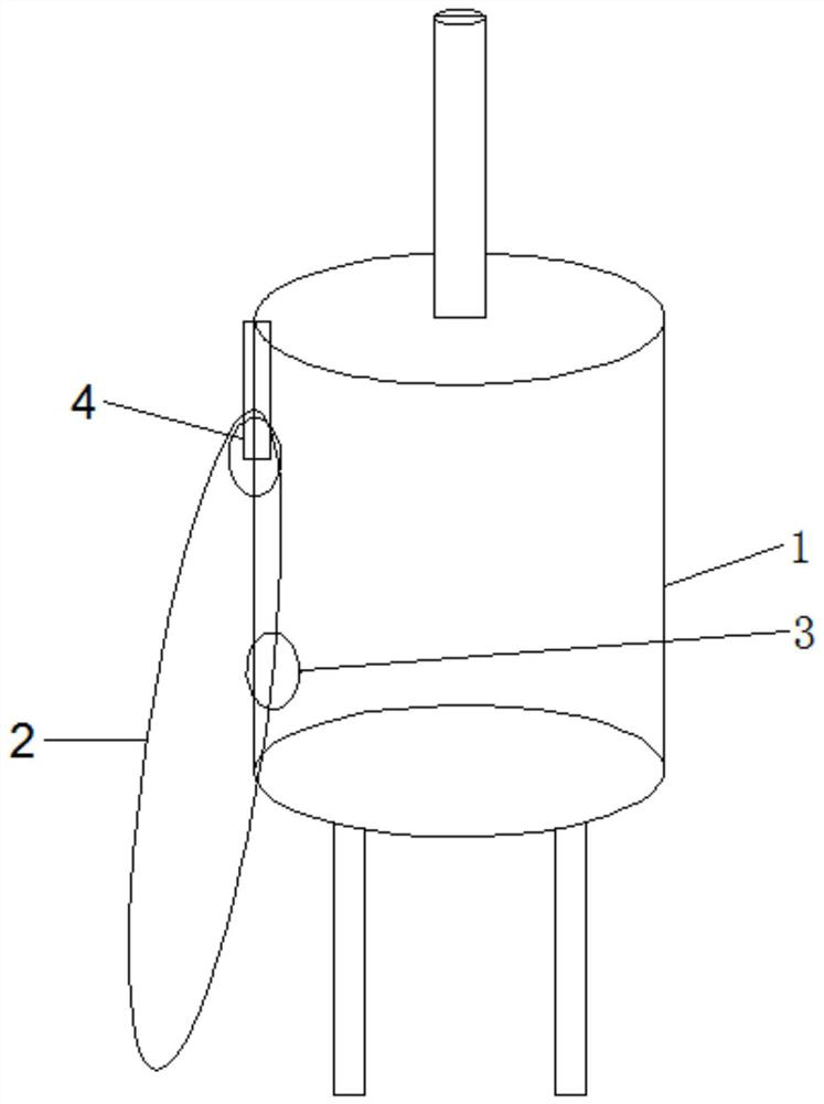
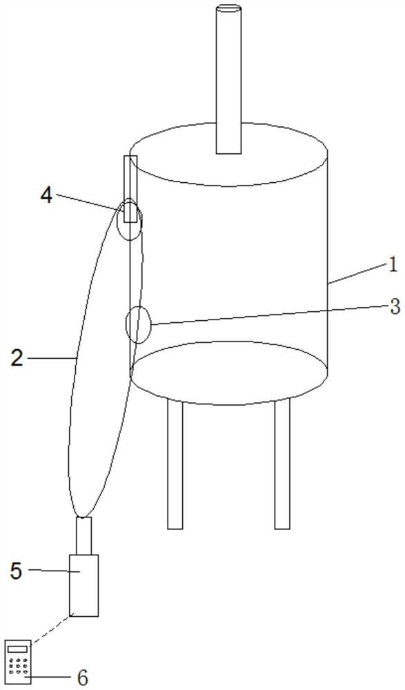
[0034] On the basis of the above structure, in this embodiment, the traction mechanism includes a rope 2 installed outside the tank body 1 and can be pulled up and down; one end of the rope 2 is fixedly connected to the impact member 3 . During detection, the worker pulls the impact piece 3 to swing through the rope 2, so that the impact piece 3 hits the outer wall of the tank body 1, and the staff can judge the amount of remaining ash in the ash tank according to the sound of the impact piece 3 hitting the tank body 1, so as to judge whether It is necessary to add ash to the ash tank to ensure the normal production.
[0035] It should be noted that when the staff manually pulls the impact member 3 through the rope 2, a certain speed is required to ensure that the impact member 3 can be thrown up, so that a certain angle is formed between the rope 2 and the outer wall of the tank body 1, thereby ensuring that the impact member 3 The outer wall of the tank body 1 can be knocked...
Embodiment 2
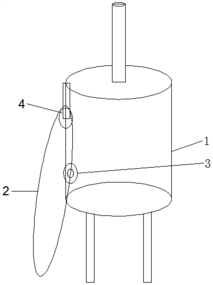
[0037] On the basis of Embodiment 1, in this embodiment, the above-mentioned tank body 1 may be a cylindrical tank body, or a rectangular tank body, or any other suitable geometric shape tank body.
Embodiment 3
[0039] On the basis of any one of Embodiment 1 to Embodiment 2, in this embodiment, the traction mechanism also includes a fixed pulley 4, and the fixed pulley 4 is vertically installed on the tank body 1, and it can rotate horizontally around its own axis; 2 bypasses the upper side of the fixed pulley 4, and slides and fits with the fixed pulley 4. During the pulling process of the rope 2, the sliding friction between the rope 2 and the tank body 1 is transformed into rolling friction between the rope 2 and the fixed pulley 4 through the fixed pulley 4, which reduces the friction force and makes the operation easier for the staff. Save time and effort, and reduce the efficiency.
[0040] Based on the above scheme, the fixed pulley 4 can be directly rotated on the tank body 1 through the rotating shaft, that is, the outer wall of the tank body 1 is provided with a groove, and the two ends of the rotating shaft are respectively connected to the two sides of the groove in rotati...
PUM
 Abstract
Description
Claims
Application Information
 - R&D Engineer
- R&D Manager
- IP Professional
- Industry Leading Data Capabilities
- Powerful AI technology
- Patent DNA Extraction
Browse by: Latest US Patents, China's latest patents, Technical Efficacy Thesaurus, Application Domain, Technology Topic, Popular Technical Reports.
© 2024 PatSnap. All rights reserved.Legal|Privacy policy|Modern Slavery Act Transparency Statement|Sitemap|About US| Contact US: help@patsnap.com