


Quick Research
Generate reliable direction feasibility study reports for your R&D in just a few steps.

Technical Q&A
Discover and master advanced knowledge NOW. Basics, ideas, possibilities, all at once.

Find Solutions
As an expert in R&D theories, this can generate solutions to your technical problems instantly.

Evaluate Feasibility
Analyze your overall solution with one click, know your potential R&D risks in advance.

Monitor Landscape
Get weekly tech updates, stay abreast of the latest tech innovations and key insights.
Underwater equipment operation monitoring system and method
A technology for underwater equipment and operation monitoring, applied in the direction of measuring devices, instruments, thermometers, etc., can solve the problems of fixed detection frequency, large influence of artificial level, difficult detection and detection of underwater equipment failures, etc.
- Summary
- Abstract
- Description
- Claims
- Application Information
AI Technical Summary
Problems solved by technology
Method used
Image

Examples
Embodiment 1
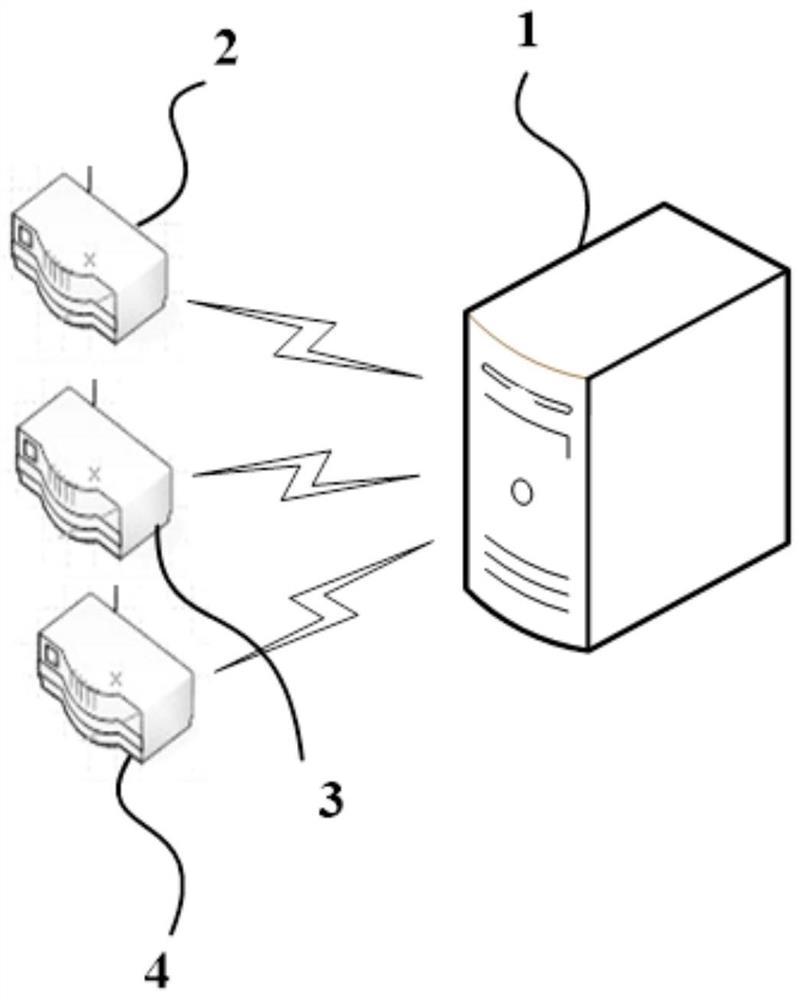
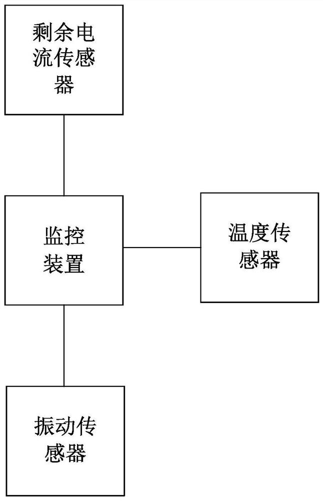
[0046] Such as Figure 1-2 As shown, a residual current monitoring system for underwater equipment includes an operation box installed on site, and the underwater equipment is connected to the switchgear installed in the operation box through a power cable, and also includes a monitoring device 1, a residual current Sensor 2, vibration sensor 3 and temperature sensor 4;
[0047]The residual current sensor 2 and the temperature sensor 4 are arranged on the power cable, the vibration sensor 3 is arranged on the underwater equipment, the residual current sensor 2, the vibration sensor 3 and the The temperature sensors 4 are respectively connected in communication with the monitoring device 1, and the monitoring device 1 is connected in communication with the switching device;
[0048] The residual current sensor 2 is used to detect the residual current of the three-phase line in the power cable in real time, obtain a residual current signal, and send the residual current signal ...
Embodiment 2
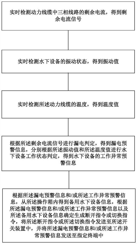
[0092] Such as image 3 As shown, a residual current monitoring method for underwater equipment, the underwater equipment is connected to the switch device in the operation box set on the site through a power cable, including the following steps:
[0093] Real-time detection of the residual current of the three-phase line in the power cable to obtain the residual current signal;
[0094] Real-time detection of the vibration state of underwater equipment to obtain the vibration value;
[0095] Detecting the temperature of the power cable in real time to obtain a temperature value;
[0096] Leakage judgment is performed according to the residual current signal, and leakage warning information and a disconnection instruction are obtained, and the leakage warning information is sent to a designated terminal, and the disconnection instruction is sent to the switch device for the switch device to Underwater equipment is closed and controlled;
[0097] Judging the working state of...
PUM
 Abstract
Description
Claims
Application Information
 - R&D Engineer
- R&D Manager
- IP Professional
- Industry Leading Data Capabilities
- Powerful AI technology
- Patent DNA Extraction
Browse by: Latest US Patents, China's latest patents, Technical Efficacy Thesaurus, Application Domain, Technology Topic, Popular Technical Reports.
© 2024 PatSnap. All rights reserved.Legal|Privacy policy|Modern Slavery Act Transparency Statement|Sitemap|About US| Contact US: help@patsnap.com