
Micro-torque rotation angle sensor and deflection angle testing method thereof

A sensor and micro-torque technology, applied in the field of inertial instruments, can solve problems such as disturbance torque, zero position offset, and unsatisfactory symmetry, and achieve the effects of reducing disturbance torque, ensuring electrical insulation reliability, and avoiding disturbance torque

Pending Publication Date: 2021-11-23
TIANJIN NAVIGATION INSTR RES INST
View PDF2 Cites 0 Cited by
  • Summary
  • Abstract
  • Description
  • Claims
  • Application Information

AI Technical Summary

Problems solved by technology

[0007] In the micro-motion synchronous configuration, since the magnetic permeable ring is located on the floating component, it is very sensitive to the radial displacement of the floating component. If the stator and rotor are not concentric or the symmetry is not ideal, radial magnetic pull and disturbance torque will be generated and The zero position of the sensor will also change accordingly, and even a very small radial displacement will introduce related disturbance moments and zero position offsets

Method used


Image

  • Micro-torque rotation angle sensor and deflection angle testing method thereof
  • Micro-torque rotation angle sensor and deflection angle testing method thereof
  • Micro-torque rotation angle sensor and deflection angle testing method thereof

Examples


Embodiment Construction

[0033] Embodiments of the present invention are described in further detail below in conjunction with the accompanying drawings:

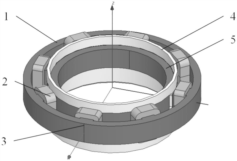
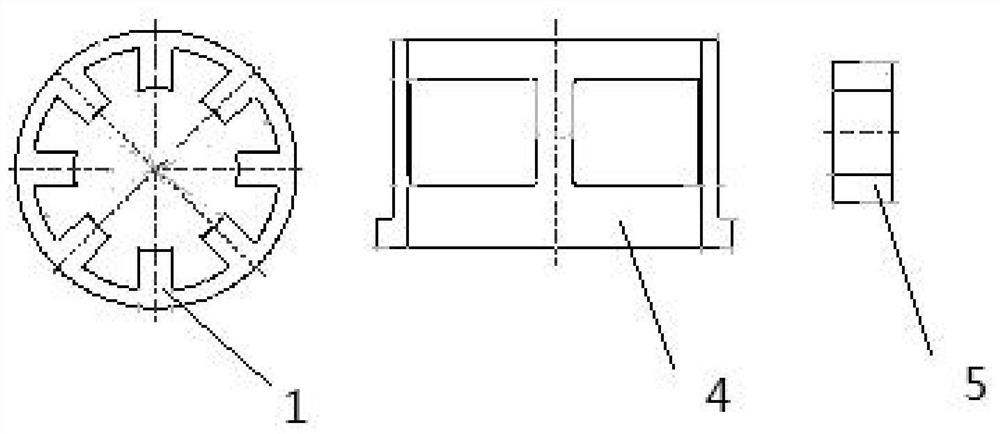
[0034] A micro-torque angle sensor, such as figure 1 As shown, it includes a stator core 1 , an output winding 2 , an excitation winding 3 , a rotor 4 and a magnetic permeable ring 5 .

[0035] The stator core 1 is installed on the fixed assembly of the gyroscope; on the annular inner wall of the stator core 1, an output winding 2 and an excitation winding 3 are installed at intervals; on the side near the axis of the output winding 2 and the excitation winding 3 The rotor is coaxially installed, and the rotor 4 is a short-circuit ring window structure, which is installed on the floating assembly of the gyroscope, and its physical position is set concentrically with the stator core 1 during operation; multiple windows are equidistant on the side wall of the rotor , the longitudinal working side 6 of the window is respectively aligned with the midl...


PUM


Abstract

The invention relates to a micro-torque rotation angle sensor and a deflection angle testing method thereof. The micro-torque rotation angle sensor comprises a stator magnetic core, an output winding, an excitation winding, a rotor and a magnetic conducting ring. The stator magnetic core is mounted on a fixing assembly of the gyroscope; an output winding and an excitation winding are installed on the annular inner wall of the stator magnetic core at intervals. A rotor is coaxially mounted on the sides, close to the axis, of the output winding and the excitation winding, the rotor is of a short circuit ring window type structure and is mounted on a floating assembly of the gyroscope, and the physical position of the rotor and a stator magnetic core are concentrically arranged during working; a plurality of windows are arranged on the side wall of the rotor at equal intervals, and the longitudinal working edges of the windows are respectively aligned with the middle line surface of the excitation winding; a magnetic conductive ring is coaxially installed on the side, close to the axis, of the rotor, the magnetic conductive ring is installed on a fixing assembly of the gyroscope, and the magnetic conductive ring, the stator magnetic core and the rotor are concentrically arranged in the working process. According to the invention, while the rotation angle of the floating assembly can be accurately sensed, the introduced disturbance torque is minimized.

Description

technical field [0001] The invention belongs to the technical field of inertial instruments, and relates to a micro-torque angle sensor, in particular to a micro-torque angle sensor for reducing the disturbance moment of a gyroscope suspension component and a deflection angle testing method thereof. Background technique [0002] Gyroscope is an angular motion sensitive element based on inertial technology, which is widely used in autonomous attitude control systems and stable platform systems. [0003] The liquid suspended rotor gyroscope is a kind of gyroscope, which takes the high-speed rotating gyro motor as the core, the rotation angle sensor as the measurement unit, and the torquer as the execution unit. The gyro motor installed in the sealed floating assembly of the gyroscope runs at high speed to generate the necessary moment of momentum. When the carrier generates angular motion along the direction of the input axis of the gyroscope, the rotor of the high-speed rotat...

Claims


Application Information

Patent Timeline
Patent Type & Authority Applications(China)
IPC IPC(8): G01C19/00
CPCG01C19/00
Inventor 武丽花赵小明聂鲁燕吴萌萌顾轩宇李毓杰
Owner TIANJIN NAVIGATION INSTR RES INST
Learn More