BIPV assembly convenient to splice
A component and convenient technology, applied in electrical components, support structures of photovoltaic modules, photovoltaic power generation, etc., can solve the problems of poor splicing efficiency, poor stability, and low assembly efficiency of BIPV components
- Summary
- Abstract
- Description
- Claims
- Application Information
AI Technical Summary
Problems solved by technology
Method used
Image
Examples
Embodiment 1
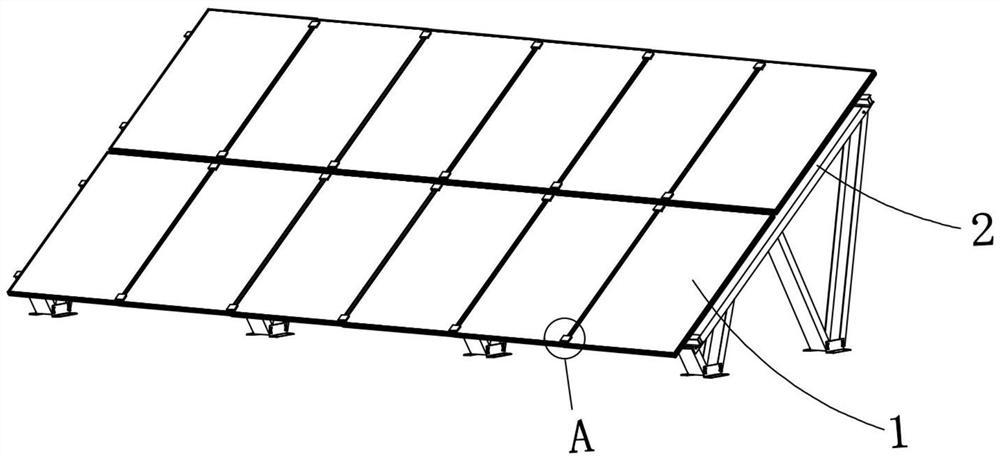
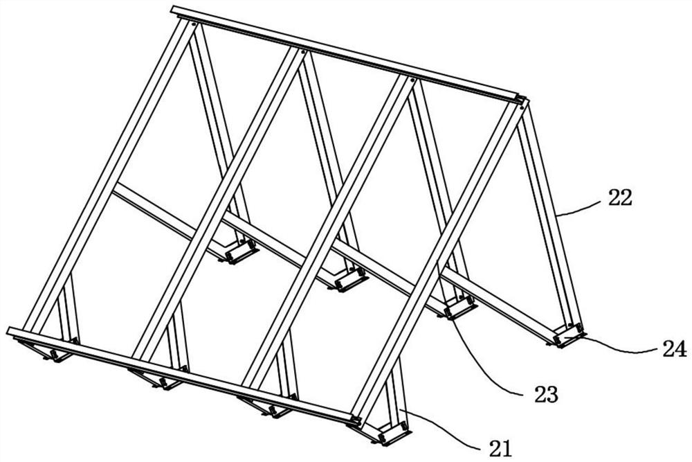
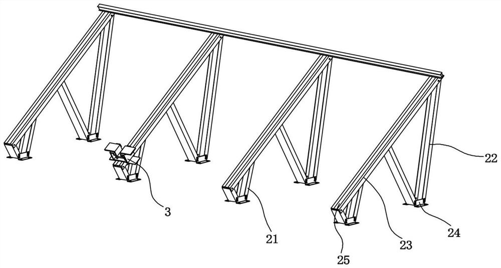
[0037] refer to Figure 1-2 A BIPV assembly that is conveniently assembled in this embodiment includes a PV assembly 1 and a support assembly 2, and the support assembly 2 includes several equal numbers of front support frames 21, rear support frames 22, support beams 23, front support frames 21, Rear support frame 22 is connected with crossbeam 23 rotations respectively, each front support frame 21, rear support frame 22 bottoms are respectively fixed with support 24, and support 24 is fixed with building roof.
[0038] Wherein, front support frame 21 and rear support frame 22 are telescopic supports, after being fixed with building roof by bearing 24, according to the style of building roof, what have is flat roof, what have is slanted roof, and then telescopic adjustment front support frame 21 and The rear support frame 22 adjusts the support assembly 2 to an appropriate inclination angle, so that the PV assembly can better receive light energy.
Embodiment 2
[0040] refer to Figure 3-7In order to facilitate the quick and convenient assembly of BIPV components, the PV module 1 is spliced and installed on the support component 2 through the installation component 3. The installation component 3 includes a concave support block 31, and a lifting plate 32 is provided inside the concave support block 31. The plate 32 includes a top plate 321 and an L-shaped plate 322 symmetrically connected to both sides of the top plate 321. The lifting plate 32 runs through the concave support block 31 and extends to the bottom of the concave support block 31. The lifting plate 32 is symmetrically rotated and connected with a buckle plate. 33, the bottom of the top plate 321 is connected to the bottom of the concave support block 31 through the first compression spring 34, the bottom of the top plate 321 passes through the first compression spring 34 and the bottom of the concave support block 31 is fixed with a connecting rod 35, and the bottom of ...
Embodiment 3
[0044] refer to Figure 6 , in order to keep the PV assembly in a stable state after splicing, in this embodiment, the two left and right pull plates 332 are connected by the second compression spring 4, and the second compression spring 4 is in a compressed state, so that under the action of the second compression spring 4 Put the two pull plates 332 close to the inside of the concave support block 31, and under the action of the non-return block 333, the pressure plate 331 and the pull plate 332 remain in a fixed state, so that the top plate 321 lifts the two L-shaped plates 322 upwards, so that the L-shaped The shape plate 322 and the pressure plate 331 block the PV assembly and keep it in a stable state. Through the buffering effect of the first compression spring 34 and the second compression spring 4, the damage to the PV assembly during the splicing process of the PV assembly can also be avoided, and the PV assembly can be effectively protected.
[0045] When the presen...
PUM
 Abstract
Description
Claims
Application Information
 - R&D
- Intellectual Property
- Life Sciences
- Materials
- Tech Scout
- Unparalleled Data Quality
- Higher Quality Content
- 60% Fewer Hallucinations
Browse by: Latest US Patents, China's latest patents, Technical Efficacy Thesaurus, Application Domain, Technology Topic, Popular Technical Reports.
© 2025 PatSnap. All rights reserved.Legal|Privacy policy|Modern Slavery Act Transparency Statement|Sitemap|About US| Contact US: help@patsnap.com


