DC bus pre-charging system

A pre-charging, bus circuit technology, applied in control systems, electrical components, AC motor control, etc., can solve problems such as difficulties

Pending Publication Date: 2021-11-19
ROCKWELL AUTOMATION TECH
View PDF0 Cites 0 Cited by
  • Summary
  • Abstract
  • Description
  • Claims
  • Application Information

AI Technical Summary

Problems solved by technology

Difficulties can arise when the precharge circuit becomes physically too large, too complex, and / or takes longer than the expected precharge time
Problems can also arise when multiple different inverter ratings exceed the maximum pre-charge capacity of a shared DC bus system

Method used


Image

  • DC bus pre-charging system
  • DC bus pre-charging system
  • DC bus pre-charging system

Examples


Embodiment Construction

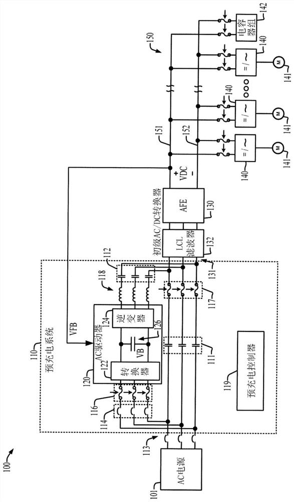
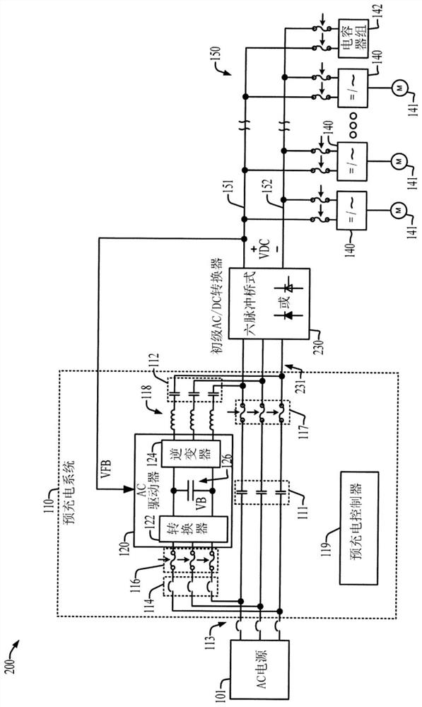
[0013] Power conversion systems typically use a shared DC bus architecture in which multiple DC loads are connected to a single bus. For example, a shared bus system may accommodate multiple inverters and one or more capacitor banks to power respective motors. High capacity systems with high power requirements may include large DC bus capacitors designed to operate at relatively high DC voltages. When starting up such a system, one or more DC bus capacitors need to be charged to a sufficient voltage for safe operation of the connected inverter or other DC load. However, simply connecting to an input voltage source to charge a capacitive load can result in excessive inrush current levels. In this regard, for example, when certain loads are disabled and / or disconnected from the shared bus, the amount of load and bus capacitance may vary. On the other hand, limiting the charge current prolongs the precharge time. Long pre-charge / start-up times are undesirable for industrial in...


PUM


Abstract

The invention discloses a DC bus pre-charging system. The DC bus pre-charging system includes a first input, a first circuit branch, a second circuit branch, and a controller. The first circuit branch includes a first contactor between the first input and the AC-to-DC converter; the second circuit branch has a disconnect switch coupled to the first input, a variable frequency driver (VFD) having an AC input coupled to the disconnect switch, an inductor coupled to an AC output of the VFD, and a second contactor coupled to the inductor. The pre-charge VFD provides precise control of pre-charge operations such as charge time, current limitation, short circuit, and ground fault protection, monitors DC bus capacitance, and verifies the health of the shared DC bus circuit by initiating diagnostics. In a first mode, the controller opens the first contactor and closes the second contactor and the open switch to pre-charge the DC bus circuit using the VFD, and in a second mode, the controller closes the first contactor and opens the second contactor and the open switch.

Description

technical field [0001] The subject matter disclosed herein relates to DC bus precharging of power conversion systems. Background technique [0002] Power conversion systems typically use a shared DC bus architecture in which multiple DC loads are connected to a single bus. For example, a shared bus system may accommodate multiple inverters and one or more capacitor banks to power respective motors. High capacity systems with high power requirements may include large DC bus capacitors designed to operate at relatively high DC voltages. When starting up such a system, one or more DC bus capacitors need to be charged to a sufficient voltage for safe operation of the connected inverter or other DC load. However, simply connecting to an input voltage source to charge a capacitive load can result in excessive inrush current levels. In this regard, for example, when certain loads are disabled and / or disconnected from the shared bus, the amount of load and bus capacitance may var...

Claims


Application Information

Patent Timeline
IPC IPC(8): H02M1/32H02M1/36H02M7/04
CPCH02M1/32H02M1/36H02M7/04H02M7/125H02M1/126H02M5/4585H02M5/42H02P27/04
Inventor 詹姆斯·J·瓦拉塞克尼奇科拉·古西科夫加雷·斯基宾斯基
Owner ROCKWELL AUTOMATION TECH
Why Eureka
Try Eureka