
Non-reciprocal optical router with planar super-lens structure based on silicon substrate integration

A non-reciprocal, super-lens technology, applied in the field of integrated optics, can solve the problems of increasing device size, modulating power consumption, increasing cascaded unit devices, and consuming modulation power, avoiding large device size, reducing overall loss, and improving Effects of connecting degrees of freedom

Active Publication Date: 2021-11-19
UNIV OF ELECTRONIC SCI & TECH OF CHINA
View PDF8 Cites 0 Cited by
  • Summary
  • Abstract
  • Description
  • Claims
  • Application Information

AI Technical Summary

Problems solved by technology

However, there is a significant restriction in such a structure, that is, this type of optical router expands the number of ports by increasing the number of cascaded unit devices
As the number of ports increases, the number of required unit devices will increase dramatically, thereby greatly increasing the device size and modulation power consumption
In addition, the currently developed optical routers are all reciprocal, that is, the connection status of forward and reverse transmission at the same time is the same, and if the transmission status is to be changed, additional modulation power needs to be consumed
[0004] Therefore, the existing integrated optical routers urgently need an easy-to-expand, small-size architecture to realize multi-port forward and reverse non-reciprocal transmission and avoid problems such as large device sizes caused by multi-port device cascading.

Method used


Image

  • Non-reciprocal optical router with planar super-lens structure based on silicon substrate integration
  • Non-reciprocal optical router with planar super-lens structure based on silicon substrate integration
  • Non-reciprocal optical router with planar super-lens structure based on silicon substrate integration

Examples


Embodiment Construction

[0023] As mentioned in the background technology section, since the transmission between a certain port pair in a conventional integrated optical router is reciprocal at the same time, the output signal and the input signal have the same path, and the forward and reverse between multiple ports cannot be realized Non-reciprocal transmission, the transmission efficiency cannot be further improved. At the same time, this type of device expands the number of ports by cascading unit devices. As the number of ports increases, the number of required unit devices will increase sharply, thereby greatly increasing the device size and modulation power consumption.

[0024] The non-reciprocal optical router with a planar metalens structure based on silicon-based integration proposed by the present invention can realize multiplex working status, improve transmission efficiency, and break the optical routing network construction method of cascading unit devices at the same time, avoiding the...


PUM


Abstract

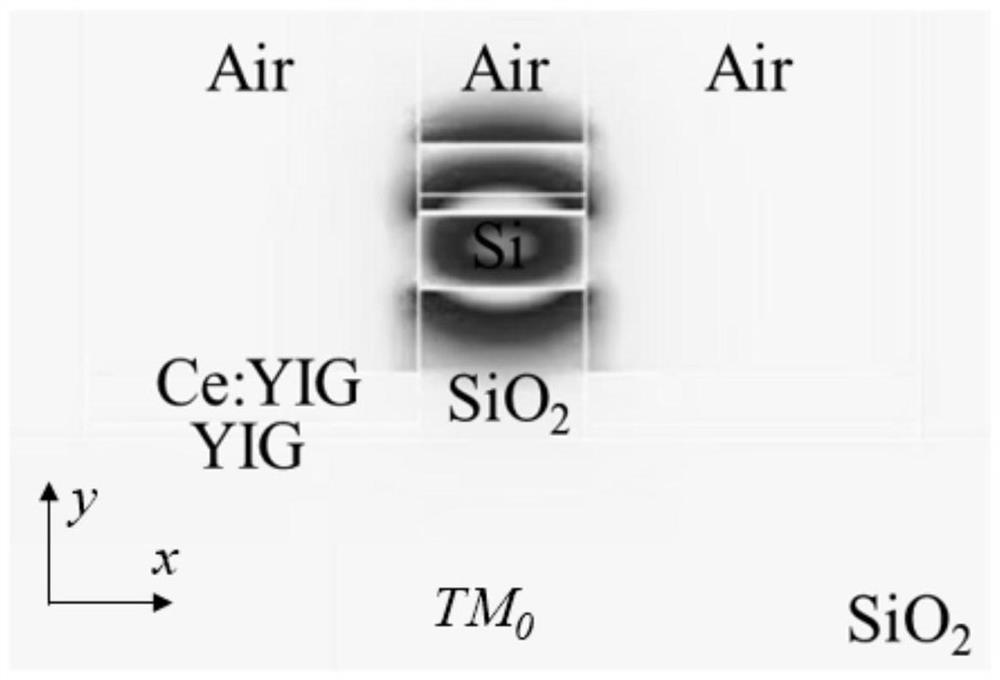
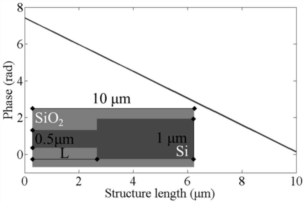
The invention belongs to the field of integrated optics, and particularly relates to a non-reciprocal optical router with a planar super-lens structure based on silicon substrate integration. According to the non-reciprocal optical router, phase design is carried out on each path of input waveguide, so that a specific phase difference is formed, and constructive interference is carried out in a required direction in the planar super lens and output is carried out; meanwhile, a non-reciprocal phase shift effect brought by a magneto-optical waveguide can enable a reverse transmission signal to be transmitted at other ports different from an input port, so that the function of simultaneously performing forward and reverse non-reciprocal optical transmission among multiple ports is realized; the port expansion does not need the cascading of devices through the method of selecting the ports through lens focusing; and finally, the transmission state is greatly expanded, and the problems of large device size and the like caused by cascade connection of multi-port devices are effectively avoided.

Description

technical field [0001] The invention belongs to the field of integrated optics, in particular to a non-reciprocal optical router based on a silicon-based integrated planar hyperlens structure. Background technique [0002] With the rapid development of information technology, the requirements for transmission bandwidth and efficiency of optical interconnection between multiple chips are constantly increasing. Silicon-based integrated optical routers have the advantages of multiple ports and high integration, which can ensure accurate transmission of information between required ports. [0003] In the existing research on integrated optical routers, a multi-port optical routing network can be formed by cascading a large number of Mach-Zehnder interference structures and microring structures. Further, phase modulation is carried out through electro-optic or thermo-optic effects in each unit structure, and the effect of switching the on-off state between multiple ports can be ...

Claims


Application Information

Patent Timeline
IPC IPC(8): G02B6/124G02B6/12H04Q11/00
CPCG02B6/1245G02B6/12004H04Q11/0005G02B2006/12038G02B2006/12085H04Q2011/0007
Inventor 毕磊严巍秦俊邓龙江
Owner UNIV OF ELECTRONIC SCI & TECH OF CHINA
Learn More