
Soil quality detection equipment for soil remediation

A detection equipment and soil remediation technology, which is applied in the field of soil remediation, can solve the problems of single function of the device, convenience, unsatisfactory adjustment and practicability, and inaccurate soil detection accuracy.

Pending Publication Date: 2021-11-19
杨强强
View PDF0 Cites 0 Cited by
  • Summary
  • Abstract
  • Description
  • Claims
  • Application Information

AI Technical Summary

Problems solved by technology

[0003] When it is necessary to test the soil quality, it can be divided into many types. Some detection devices directly put the soil sample on a container, and use microscopes and other instruments to observe. The function of the device is single, and some use HP value sensors, GPS soil moisture temperature speed measuring instrument, soil salinity measuring instrument and other instruments can detect the soil quality. However, when the operator manually holds the HP value sensor to detect the quality of the soil, it is easy to cause arm pain for a long time. When the HP value sensor is used, the adjustment is more troublesome, and when the operator detects the soil, if the soil is not loose and agglomerated, it is easy to cause inaccurate detection accuracy of the soil, which makes the overall convenience, adjustment and practicability unsatisfactory

Method used


Image

  • Soil quality detection equipment for soil remediation
  • Soil quality detection equipment for soil remediation
  • Soil quality detection equipment for soil remediation

Examples


Embodiment Construction

[0031] The following will clearly and completely describe the technical solutions in the embodiments of the present invention with reference to the accompanying drawings in the embodiments of the present invention. Obviously, the described embodiments are only some, not all, embodiments of the present invention. Based on the embodiments of the present invention, all other embodiments obtained by persons of ordinary skill in the art without making creative efforts belong to the protection scope of the present invention.

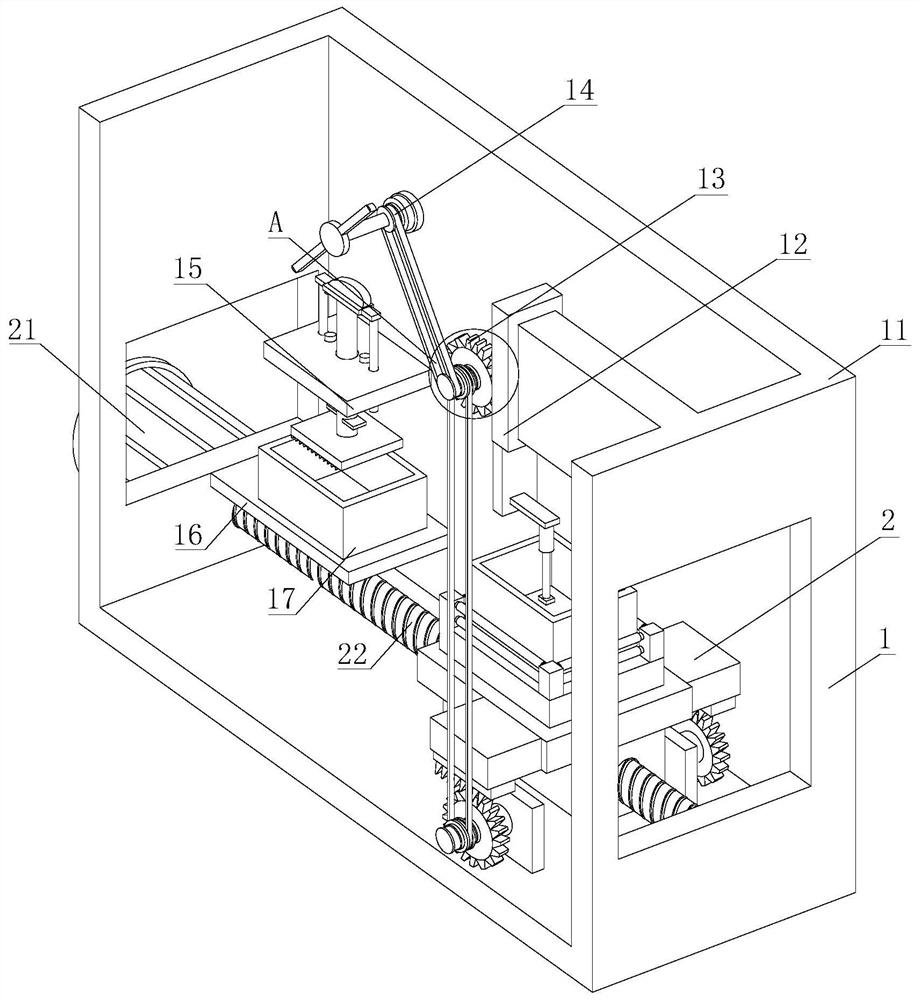
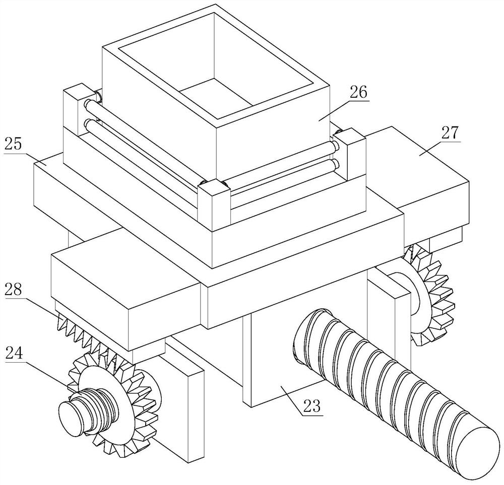
[0032] see Figure 1-2 , a kind of soil quality testing equipment for soil remediation, comprising a device body 1 and a carrying mechanism 2, the carrying mechanism 2 is installed at the lower end of the inner cavity of the device body 1, and the device body 1 includes a casing 11, a lifting assembly 12, a transmission assembly 13, and a rotating assembly 14. The crushing assembly 15, the bottom plate 16 and the pretreatment box 17, the lifting assembly 12 is...


PUM


Abstract

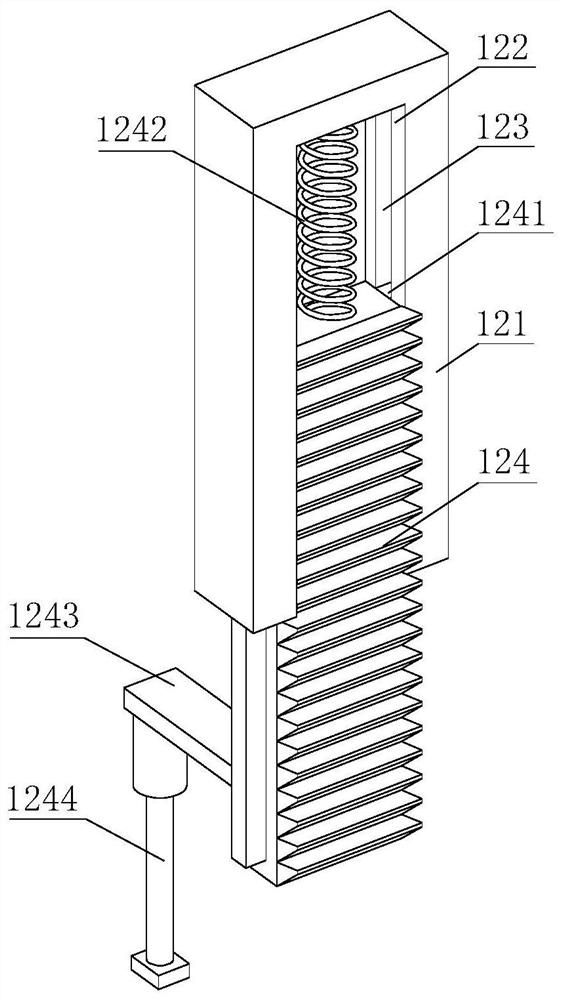
The invention discloses soil quality detection equipment for soil remediation. The soil quality detection equipment comprises a device body and a bearing mechanism, the surface of a fixed cross rod is sleeved with a rolling sleeve, when a material containing box needs to be installed or taken out, the rolling sleeve assists in rolling on the outer wall of the material containing box, so that the material containing box is convenient to install or take out, meanwhile, the material containing box is prevented from shaking and displacing at the upper end of the supporting plate, when a driven wheel drives a driven gear to rotate through a connecting shaft, the driven gear is meshed with a vertical toothed plate on one side of the driven gear, and when the vertical toothed plate is meshed with the driven gear, the vertical toothed plate descends on the inner side of the fixed outer frame; when the vertical toothed plate descends downwards, the vertical toothed plate drives a PH sensor to reach the inner side of the material containing box through a connecting plate on one side to detect soil, when an abutting rod rotates to the lower end of a circular plate, the abutting rod abuts against and extrudes an arc-shaped top plate, and the arc-shaped top plate drives a positioning connecting rod to move downwards; and the positioning connecting rod crushes the soil coagulated into blocks on the inner side of the pretreatment box through the crushing pressing plate.

Description

technical field [0001] The invention relates to the technical field of soil remediation, in particular to a soil quality detection device for soil remediation. Background technique [0002] Soil environment monitoring refers to determining the environmental quality (or pollution degree) and its change trend through the determination of representative values ​​of factors affecting soil environmental quality. What we usually call soil monitoring refers to soil environment monitoring, which generally includes point sampling, Technical content such as sample preparation, analysis method, result characterization, data statistics and quality evaluation. [0003] When it is necessary to test the soil quality, it can be divided into many types. Some detection devices directly put the soil sample on a container, and use microscopes and other instruments to observe. The function of the device is single, and some use HP value sensors, GPS soil moisture temperature speed measuring inst...

Claims


Application Information

Patent Timeline
Patent Type & Authority Applications(China)
IPC IPC(8): G01N33/24
CPCG01N33/24
Inventor 杨强强
Owner 杨强强
Learn More