
Mold for injection molding

An injection molding and mold technology, applied in the field of injection molding molds, can solve the problems of easy entry of dust and impurities into the mold cavity, raw materials spilling on the working surface, affecting the efficiency of work, etc., and achieve the effect of being conducive to falling off and blocking Good, improve the effect of efficiency

Active Publication Date: 2021-11-19
佛山市顺德区天玛仕电子有限公司
View PDF8 Cites 0 Cited by
  • Summary
  • Abstract
  • Description
  • Claims
  • Application Information

AI Technical Summary

Problems solved by technology

After the upper mold and the lower mold are engaged, there will be a gap at the joint, and the gap is connected with the cavity, so that external dust and impurities can easily enter the cavity, and the residual impurities inside the cavity will affect the subsequent products. , which reduces the quality of the product
During the placement of the mold, the external dust will also enter the interior of the mold cavity, and the mold needs to be cleaned when the mold is used again, which will affect the efficiency of the work
Moreover, if there are too many raw materials inside the cavity, it is easy to leak from the connection, causing the raw materials to spill on the working surface, requiring follow-up cleaning, causing inconvenience to normal work

Method used


Image

  • Mold for injection molding
  • Mold for injection molding
  • Mold for injection molding

Examples


Embodiment Construction

[0029] The technical solutions of the present invention will be clearly and completely described below in conjunction with the embodiments. Apparently, the described embodiments are only some of the embodiments of the present invention, not all of them. Based on the embodiments of the present invention, all other embodiments obtained by persons of ordinary skill in the art without creative efforts fall within the protection scope of the present invention.

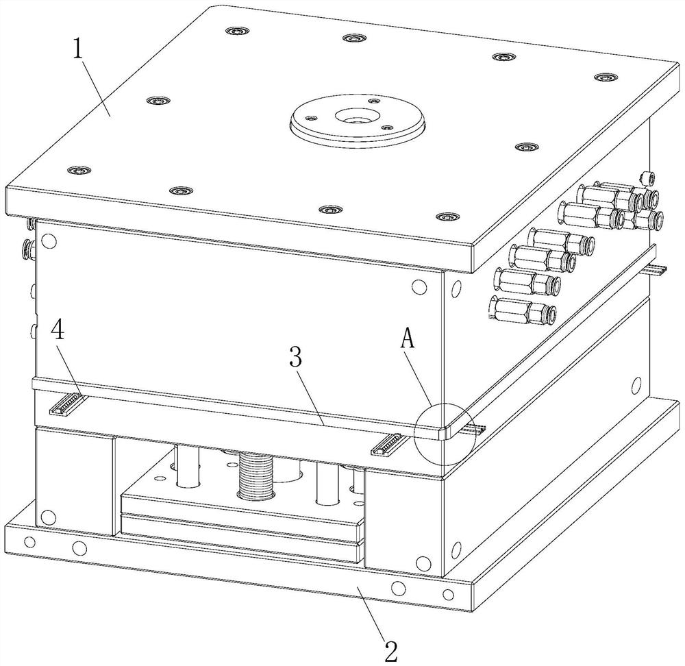
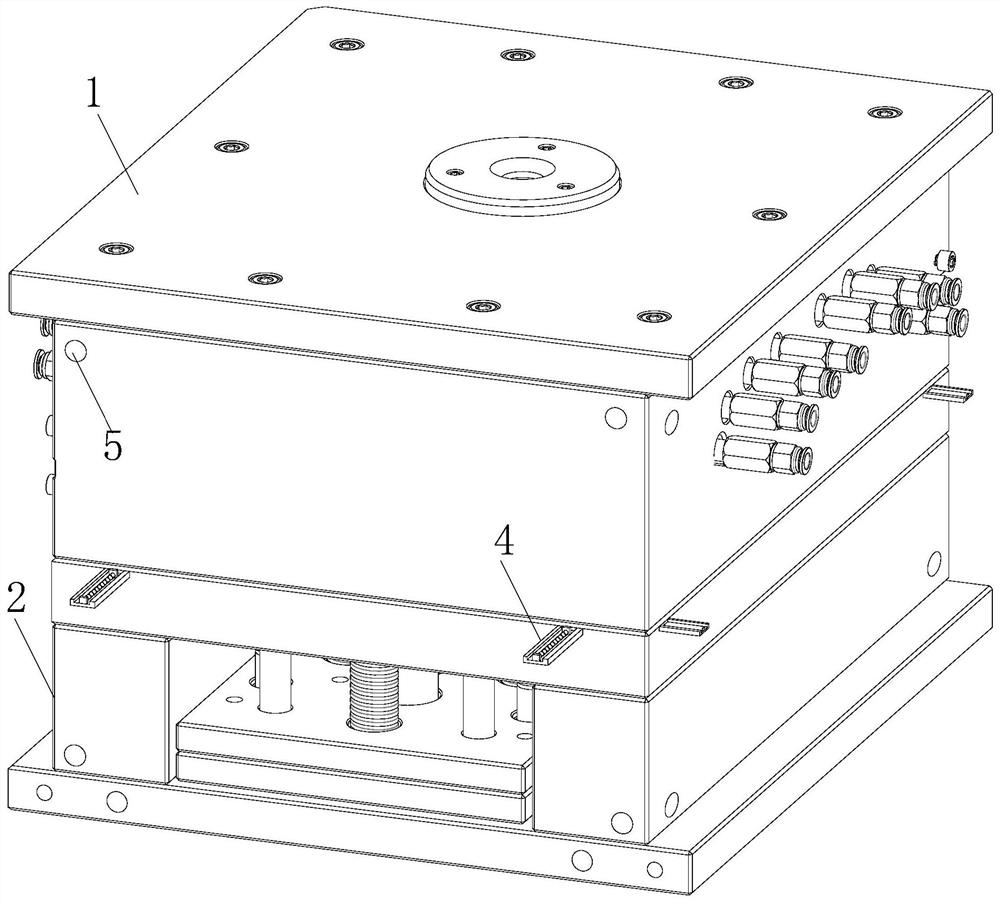
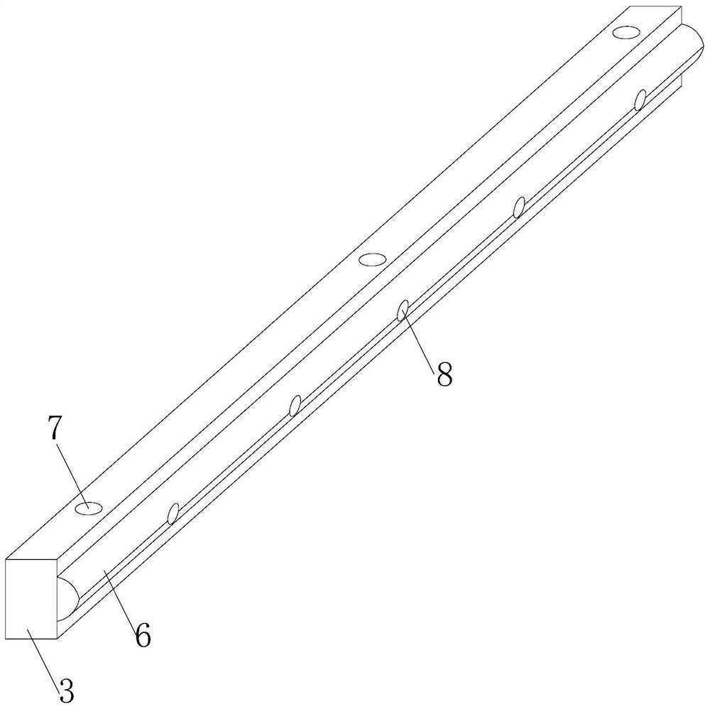
[0030] see Figure 1-9 As shown, a mold for injection molding includes an upper mold 1 and a lower mold 2, the upper mold 1 is installed above the lower mold 2, and a sealing mechanism is arranged above the lower mold 2, and the sealing mechanism includes a blocking plate 3 and a sealing gasket 6.

[0031] The top of the lower mold 2 is slidably installed with a sealing plate 3 around it, and the side of the sealing plate 3 facing the lower mold 2 is connected with a gasket 6, and both ends of the upper side of the lower m...


PUM


Abstract

The invention relates to the field of molds, in particular to a mold for injection molding. The mold comprises an upper mold and a lower mold, the upper mold is installed above the lower mold, a sealing mechanism is arranged above the lower mold and comprises blocking plates and sealing gaskets, blocking plates are slidably installed on the periphery of the upper portion of the lower mold, the sealing gaskets are connected to the sides, facing the lower mold, of the blocking plates, transverse plates are horizontally connected to the two ends of the side face of the upper portion of the lower mold, the blocking plates are slidably installed above the transverse plates, and sliding grooves are formed in the interiors of the transverse plates in the sliding direction of the blocking plates. When the mold is not used, dust cannot enter a space between the upper mold and the lower mold easily through the sealing gaskets, cleaning is not needed during subsequent reuse, the step of cleaning the mold is omitted, when the blocking plates move to the joint between the upper mold and the lower mold, the end part is blocked through an elastic plate, blocking between the upper mold and the lower mold is more sufficient and comprehensive, and the blocking effect is better.

Description

technical field [0001] The invention relates to the field of molds, in particular to a mold for injection molding. Background technique [0002] Injection mold is a tool for producing plastic products; it is also a tool for giving plastic products complete structure and precise dimensions. Injection molding is a processing method used in the mass production of certain complex-shaped parts. Specifically, it refers to injecting the heated and melted plastic into the mold cavity under high pressure from the injection molding machine, and after cooling and solidifying, a molded product is obtained. [0003] Injection molds are usually divided into upper mold and lower mold. After the upper mold and lower mold are engaged, the raw materials are formed. After the upper mold and the lower mold are engaged, there will be a gap at the joint, and the gap is connected with the cavity, so that external dust and impurities can easily enter the cavity, and the residual impurities inside...

Claims


Application Information

Patent Timeline
Patent Type & Authority Applications(China)
IPC IPC(8): B29C45/26B29C45/34B29C45/17
CPCB29C45/2608B29C45/34B29C45/1744B29C45/1753
Inventor 白青霞岑欢
Owner 佛山市顺德区天玛仕电子有限公司
Learn More