
A nozzle orientation vector control structure

A nozzle and vector technology, which is applied in the field of nozzle azimuth vector control structure, can solve the problems that the spray direction is not easy to change, and the spray direction cannot be automatically calibrated.

Active Publication Date: 2022-02-08
气味王国(山东)科技有限公司
View PDF10 Cites 0 Cited by
  • Summary
  • Abstract
  • Description
  • Claims
  • Application Information

AI Technical Summary

Problems solved by technology

[0002] The odor vortex directional emitter is a device used to emit the odor vortex. In the prior art, the injection direction of the nozzle of the odor vortex directional emitter is fixed and difficult to change, and the injection direction cannot be automatically calibrated.

Method used


Image

  • A nozzle orientation vector control structure
  • A nozzle orientation vector control structure
  • A nozzle orientation vector control structure

Examples


Embodiment Construction

[0019] The present invention will be further described in detail below in conjunction with the accompanying drawings and specific embodiments.

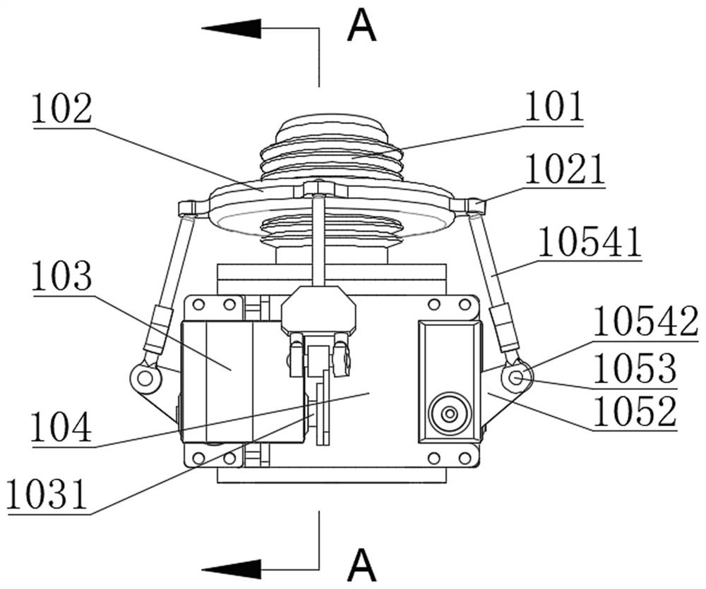
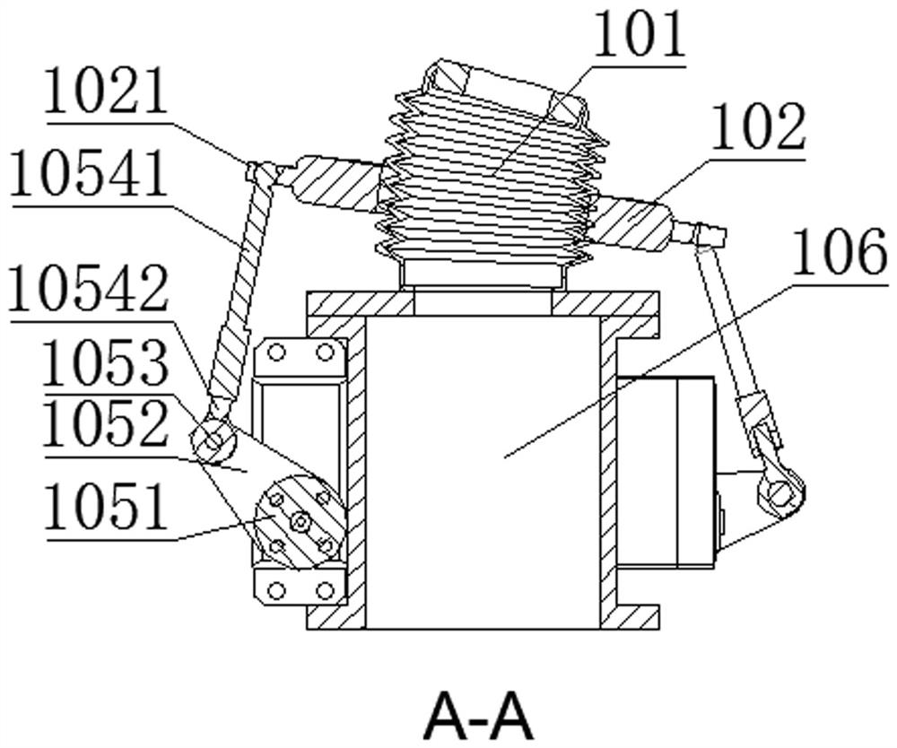
[0020] Such as Figure 1-4 As shown, a nozzle orientation vector control structure includes a corrugated nozzle 101 , an amplitude modulation ring 102 , four steering gears 103 and a steering gear mounting seat 104 .

[0021] The circumference of the amplitude modulation ring 102 is integrally provided with four evenly arranged amplitude modulation ring connecting ears 1021 , and the amplitude modulation ring connecting ears 1021 are respectively connected to one steering gear 103 through a crank linkage mechanism 105 .

[0022] The inner ring of the amplitude modulation ring 102 is clamped on the middle section of the corrugated nozzle 101 . One end of the corrugated nozzle 101 is fixed, and the gas is ejected from the other end of the corrugated nozzle 101 .

[0023] The steering gear mounting base 104 is fixedly connected to the ...


PUM


Abstract

The invention provides a nozzle orientation vector control structure, which includes a corrugated nozzle, an amplitude modulation ring and several steering gears; The connection positions are different, and each crank connection mechanism adjusts the height of different connection positions of the amplitude modulation ring, so that the inclination angle of the amplitude modulation ring is variable, and the amplitude modulation ring is clamped outside the corrugated nozzle. In the nozzle azimuth vector control structure, the steering gear drives the connecting crank of the rudder disc to rotate, and the connecting crank of the rudder disc drives the connecting rod to rotate, and then changes the height position of the connecting ear of the amplitude modulation ring connected to the connecting rod. According to the inclination angle of the AM ring, the four steering gears raise or lower the connecting ear of the AM ring according to different height requirements, and the inclination angle of the AM ring changes accordingly. After the inclination angle of the amplitude modulation ring is changed, the bending angle of the corrugated nozzle is also changed, thereby changing the jetting angle of the gas.

Description

technical field [0001] The invention belongs to the technical field of gas injection, and in particular relates to a nozzle orientation vector control structure. Background technique [0002] The scent vortex directional emitter is a device for emitting the scent vortex. In the prior art, the spray direction of the nozzle of the scent vortex directional emitter is fixed and difficult to change, and the spray direction cannot be automatically calibrated. Contents of the invention [0003] The present invention aims to solve the above-mentioned technical problems, and provides a nozzle azimuth vector control structure. [0004] In order to achieve the above object, the present invention adopts following technical scheme: [0005] A nozzle orientation vector control structure, including a corrugated nozzle, an amplitude modulation ring, and several steering gears; the steering gears are respectively connected to the amplitude modulation ring through a crank linkage mechanism...

Claims


Application Information

Patent Timeline
Patent Type & Authority Patents(China)
IPC IPC(8): G05D3/12
CPCG05D3/12
Inventor 陈源黄剑炜连加俤许静潘永健
Owner 气味王国(山东)科技有限公司
Learn More