Road surface finishing machine

A finishing machine and hydraulic component technology, applied in the field of road finishing machines, can solve problems such as uneven road surface, rubber wheel wear, steering wheel slipping, etc.

Inactive Publication Date: 2004-01-28
ABG ALLG BAUMASCHINEN GMBH
View PDF0 Cites 1 Cited by
  • Summary
  • Abstract
  • Description
  • Claims
  • Application Information

AI Technical Summary

Problems solved by technology

[0005] If from now on the steering wheel itself is equipped with a drive, this will inevitably lead to slippage of the deloaded steering wheel, which not only creates traction problems but also creates uneven forward speeds (due to uneven compaction of the road surface)
In addition, the steering wheel that is skidding (the wheel is idling at high speed) will cause huge wear to t...

Method used


Image

  • Road surface finishing machine
  • Road surface finishing machine
  • Road surface finishing machine

Examples


Embodiment Construction

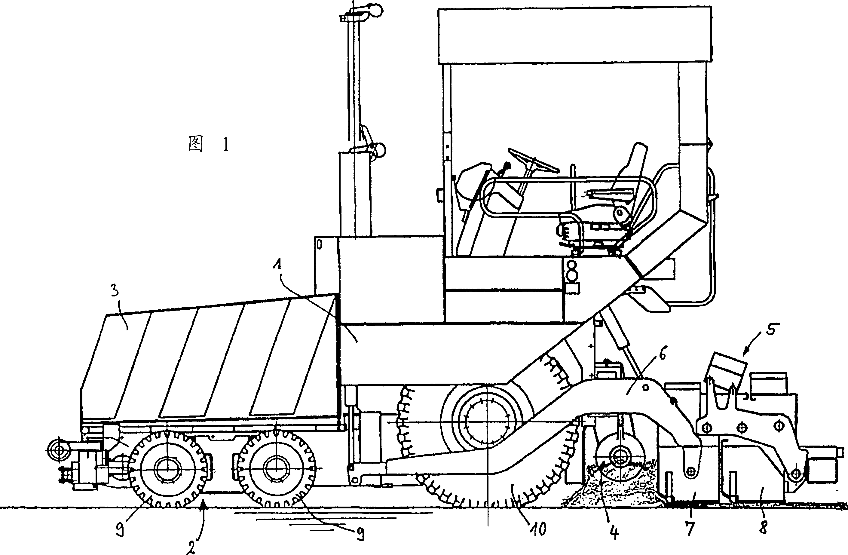
[0012] The illustrated road finishing machine comprises a chassis 1 with a wheel-driven traveling device 2, a hopper 3 at the front of the chassis 1, and a screw paver 4 at the rear, between the hopper 3 and the screw paver. A conveyor belt (not visible in the figure) is arranged between the paver 4 for conveying the mixed material to be laid from the hopper 3 via a delivery shaft to the area of ​​the paver screw 4 . The superstructure of the road finishing machine is located above the haul shaft.

[0013] A laying plate 5 for floating laying of the mixed material to be laid is hinged on the chassis 1 via tie rods 6 . The laying board 5 is located behind the spiral paver 4 along the laying direction, and includes a base plate 7 and a stretching board 8 . These stretch plates 8 can be stretched laterally relative to the base plate and independently of each other. The base plate 7 is usually split in the middle, and the two halves of the base plate can be inclined relative to ...


PUM


Abstract

The invention provides a road surface finishing machine including a frame (1) and multiple wheels (2). Multiple wheels (2) include two steering front wheels (9) and one or two driving wheels (10) provided on both sides, the driven and undriven steering front wheels (9) are supported on the frame (1), and they are suspended by pneumatic or hydraulic elements (11,12) communicated and connected together to unify the pressure.

Description

technical field [0001] The invention relates to a road finisher equipped with wheels. Background technique [0002] A wheeled road finishing machine usually has one or two steering wheels on each side at the front, in addition to the drive wheels at the rear (one or two on each side), under the hopper that holds the material to be paved . [0003] In order to obtain a good self-leveling performance (which is necessary for laying a level surface and to distribute the load evenly on the steering wheels), it is known that in the case of road finishing machines with four steering wheels, each In the case of two steered wheels on one side, the steered wheels on one side are mounted in a connecting rocker acting in the longitudinal direction with respect to the direction of travel. [0004] When the road surface is uneven in the direction of travel, a satisfactory level compensation can be produced with a rocker arm which also acts in the direction of travel. When there is an u...

Claims


Application Information

Patent Timeline
IPC IPC(8): B60G21/06E01C19/48
CPCB60G21/06E01C19/48
Inventor 德克・海姆斯
Owner ABG ALLG BAUMASCHINEN GMBH
Why Eureka
Try Eureka