
Antenna polarity switching method, antenna module and electronic equipment

A technology for antenna modules and electronic equipment, which is applied to antennas, antenna arrays, circuits, etc., can solve the problems of increasing the stacking thickness of electronic equipment, large internal space of electronic equipment, and the occupancy of switchable polarity antennas, so as to reduce the overall Machine stacking thickness, which is conducive to thin and light design, and the effect of releasing internal space

Pending Publication Date: 2021-11-09
VIVO MOBILE COMM CO LTD
View PDF0 Cites 3 Cited by
  • Summary
  • Abstract
  • Description
  • Claims
  • Application Information

AI Technical Summary

Problems solved by technology

[0004] The purpose of the embodiments of the present application is to provide an antenna polarity switching method, antenna module and electronic equipment, which can solve the problem that the existing switchable polarity antenna occupies a large amount of internal space of the electronic equipment and increases the stacking of the whole electronic equipment. Thickness Technical Issues

Method used


Image

  • Antenna polarity switching method, antenna module and electronic equipment
  • Antenna polarity switching method, antenna module and electronic equipment
  • Antenna polarity switching method, antenna module and electronic equipment

Examples


Embodiment Construction

[0023] The following will clearly and completely describe the technical solutions in the embodiments of the present application with reference to the drawings in the embodiments of the present application. Obviously, the described embodiments are part of the embodiments of the present application, not all of them. Based on the embodiments in this application, all other embodiments obtained by persons of ordinary skill in the art without creative efforts fall within the protection scope of this application.

[0024] The terms "first", "second" and the like in the specification and claims of the present application are used to distinguish similar objects, and are not used to describe a specific sequence or sequence. It is to be understood that the data so used are interchangeable under appropriate circumstances such that the embodiments of the application can be practiced in sequences other than those illustrated or described herein. In addition, "and / or" in the specification an...


PUM


Abstract

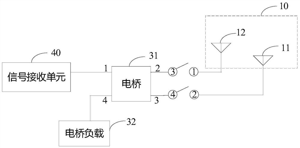
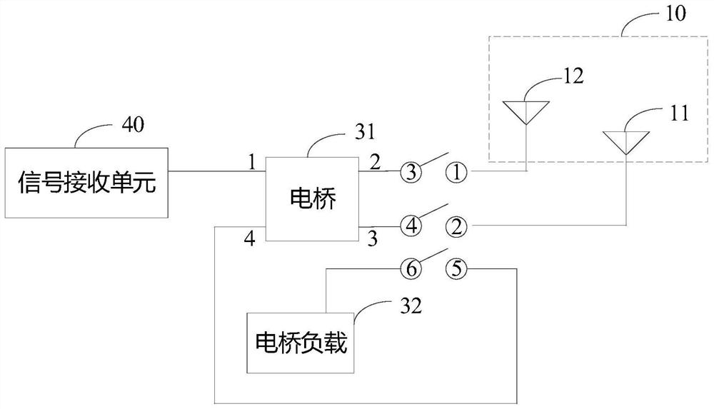
The invention provides an antenna polarity switching method, an antenna module and electronic equipment. The antenna module comprises an antenna unit, a first switch unit, a phase converter and a signal receiving unit; the antenna unit comprises a first antenna and a second antenna, the first antenna is connected with the first end of the first switch unit, and the second antenna is connected with the second end of the first switch unit; the third end of the first switch unit is connected with the first input end of the phase converter, and the fourth end of the first switch unit is connected with the second input end of the phase converter; and the output end of the phase converter is connected with the signal receiving unit. The antenna module in the embodiment of the invention is composed of a small number of components, and the circuit structure is simple, so the internal space of the electronic equipment is released, the whole machine stacking thickness of the electronic equipment is reduced, and the light and thin design of the electronic equipment is facilitated.

Description

technical field [0001] The present application belongs to the technical field of antennas, and in particular relates to an antenna polarity switching method, an antenna module and electronic equipment. Background technique [0002] At present, electronic devices usually use antennas to receive satellite signals transmitted by the Global Navigation Satellite System (GNSS) to accurately locate the electronic devices. Wherein, the polarization direction of the satellite signal is right-handed circular polarization. In order to ensure that the electronic device can accurately receive the satellite signal in various holding states, the electronic device usually uses an antenna with switchable polarity to receive the satellite signal. [0003] In the prior art, the switchable polarity antenna has a large number of components and a relatively complicated structure, which causes the existing switchable polarity antenna to occupy a large amount of internal space of the electronic dev...

Claims


Application Information

Patent Timeline
Patent Type & Authority Applications(China)
IPC IPC(8): H01Q21/00H01Q3/38
CPCH01Q21/00H01Q3/38
Inventor 黄润鹏谢毅华
Owner VIVO MOBILE COMM CO LTD
Learn More