Container bag transfer equipment for grain and oil grain storage
A container bag and grain technology, which is applied in the direction of freight vehicles, packaging, transport objects, etc., can solve the problems of difficult transportation, bursting, etc.
- Summary
- Abstract
- Description
- Claims
- Application Information
AI Technical Summary
Problems solved by technology
Method used
Image
Examples
Embodiment 1
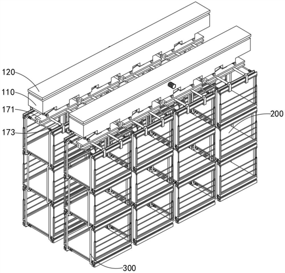
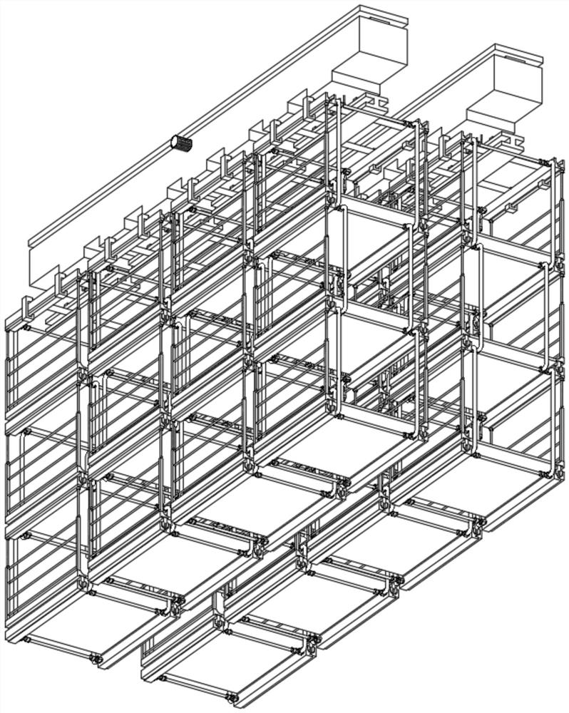
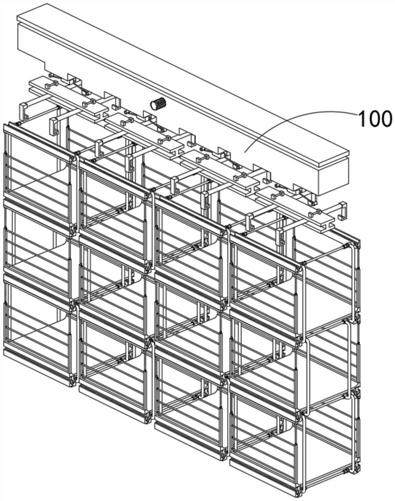
[0048] combine Figure 5 , 6 , 7 and 9, a kind of container bag transfer equipment for grain, oil and grain storage provided by the present invention includes a lifting transmission mechanism 100, a container bag transfer mechanism 200 and a load-bearing member 300, wherein the lifting transmission mechanism 100 passes through the The rope is connected to the container bag transfer mechanism 200 , and the other 300 is installed on the load-bearing member 200 .
[0049] The lifting transmission mechanism 100 includes an extension cabinet 110, a fixed top plate 120, a transmission shaft 130, a reverse rotating shaft 140, an auxiliary shaft 150, a slide bar 160, and an electromagnetic compression assembly 170, and the 170 also includes a load-bearing member 171, an electromagnet 172, and a bracket 173, wherein the container bag transfer mechanism 200 includes a top-loading combination 210, a middle-loading combination 220, a bottom-loading combination 230 and a support 240, and ...
Embodiment 2
[0052] combine Figure 5 As shown, in the above-mentioned embodiment, the slider at the bottom of the fixed top plate 120 is used to fit with the Huacao at the top of the extension chassis 110, and at the same time, the slider at the top side of the extension chassis 110 is inserted into the groove at the bottom of the fixed top plate 120 , at this time, the operator can transfer the container bag by controlling the lateral movement of the stretching chassis 110, and use the reverse rotating shaft 140 engaged on the outside as the auxiliary transmission end. At this time, the ropes in the stretching chassis 110 are in reverse lifting and releasing state, and an auxiliary shaft 150 is connected to the transmission shaft 130 by a chain, and the difference in rotation direction between the three auxiliary shafts 150, the reverse rotation shaft 140 and the transmission shaft 130 is used to constrain the rope, stretch and lift The part also includes a fixed top plate 120 installed ...
Embodiment 3
[0054] combine Image 6 As shown, in the above-mentioned embodiment, when the internal servo motor of the transmission shaft 130 is running, its internal gear rod will simultaneously drive the reverse rotation shaft 140 and the three auxiliary shaft rods 150, so as to realize the simultaneous tightening and release of the rope, and will The electromagnetic compression combination 171 is flexibly connected with the ropes in the inner cavity of the stretching case 110. When the ropes in the inner cavity of the stretching chassis 110 are pulled, they are acted on by the auxiliary shaft 150. At this time, the electromagnetic compression combination 171 can be fastened by the ropes. Lifting and release, when the electromagnet 172 is affected by the current and produces a magnetic field that repels and attracts each other with the permanent magnet in the bracket 173, the U-shaped clamping block in the bracket 173 can be quickly clamped to the rectangular shape in the stabilizer 217. ...
PUM
 Abstract
Description
Claims
Application Information
 - R&D Engineer
- R&D Manager
- IP Professional
- Industry Leading Data Capabilities
- Powerful AI technology
- Patent DNA Extraction
Browse by: Latest US Patents, China's latest patents, Technical Efficacy Thesaurus, Application Domain, Technology Topic, Popular Technical Reports.
© 2024 PatSnap. All rights reserved.Legal|Privacy policy|Modern Slavery Act Transparency Statement|Sitemap|About US| Contact US: help@patsnap.com


