Locking and separating disassembly and assembly structure of drawer panel

A lock-off and panel technology, which is applied to drawers, furniture parts, household appliances, etc., can solve the problems of complex mechanism, poor user experience, damage and high failure rate, and achieve the effect of simplifying the structure of disassembly and assembly and stabilizing disassembly and assembly

Pending Publication Date: 2021-11-09
GUANGDONG DTC HARDWARE PRECISION MFG CO LTD
View PDF1 Cites 0 Cited by
  • Summary
  • Abstract
  • Description
  • Claims
  • Application Information

AI Technical Summary

Problems solved by technology

However, the above-mentioned mechanism simultaneously releases the separation of the upper and lower locking devices from the two connecting parts through a single active part, so the user needs to overcome the locking force of the two locking devices acting on the two connecting parts at the same time during use. , that is, the user needs to apply a large force to complete the separation of the drawer panel. At the same time, the size of the active part is large and the active position is long, so that the user needs to spend more time to apply a greater force on the active part to make it Rotation, resulting in extremely poor user experience; and in order to unlock the two locking devices at the same time, the entire mechanism is quite complicated, the number of components is large, and the requirements for production and assembly processes are high. Damage to individual components will cause the entire product to be unable to use normally , the damage and failure rate is quite high

Method used


Image

  • Locking and separating disassembly and assembly structure of drawer panel
  • Locking and separating disassembly and assembly structure of drawer panel
  • Locking and separating disassembly and assembly structure of drawer panel

Examples


Embodiment Construction

[0045] The present invention will be further described below in conjunction with the accompanying drawings and embodiments.

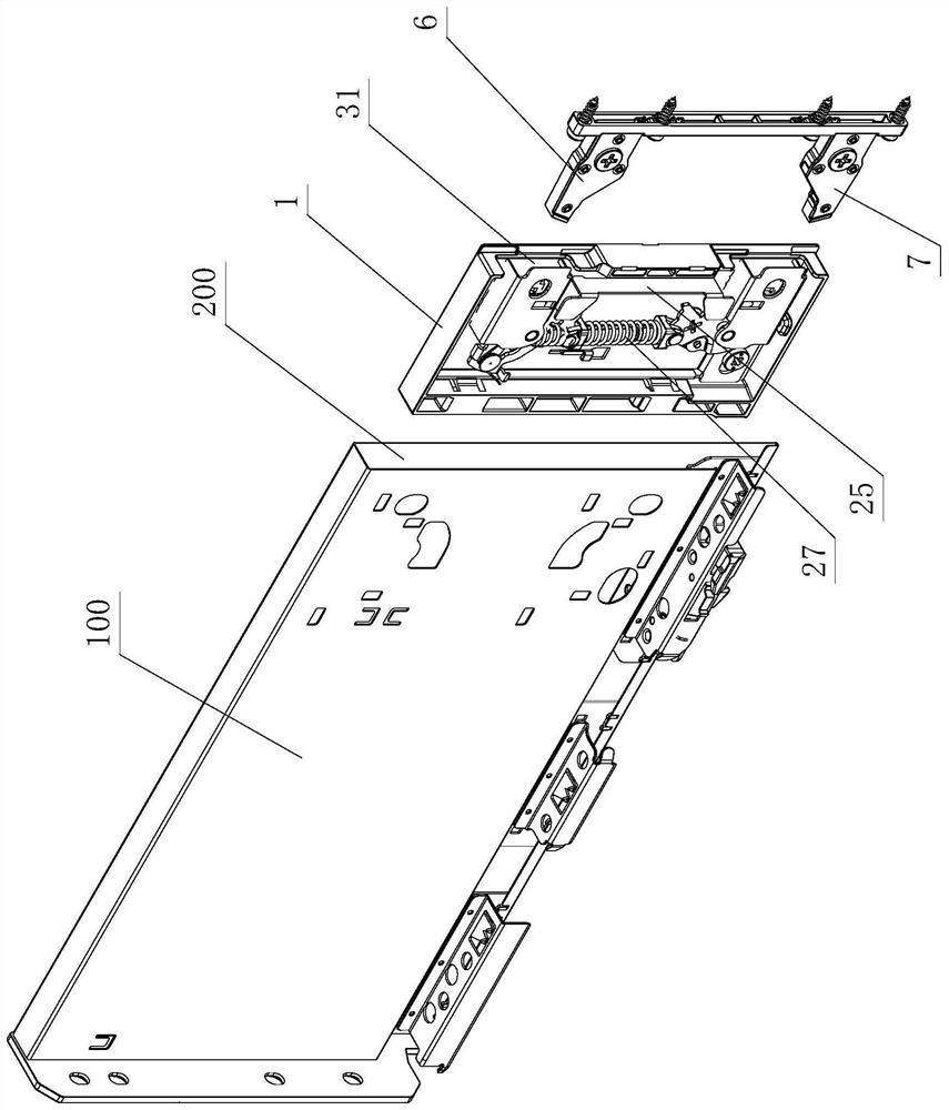
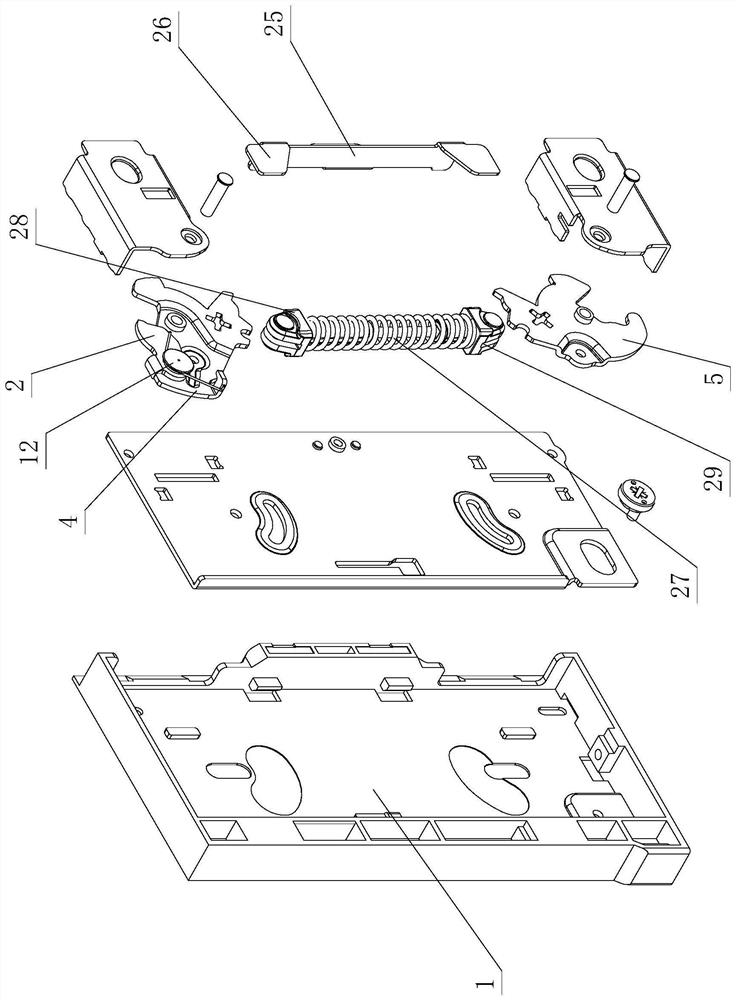
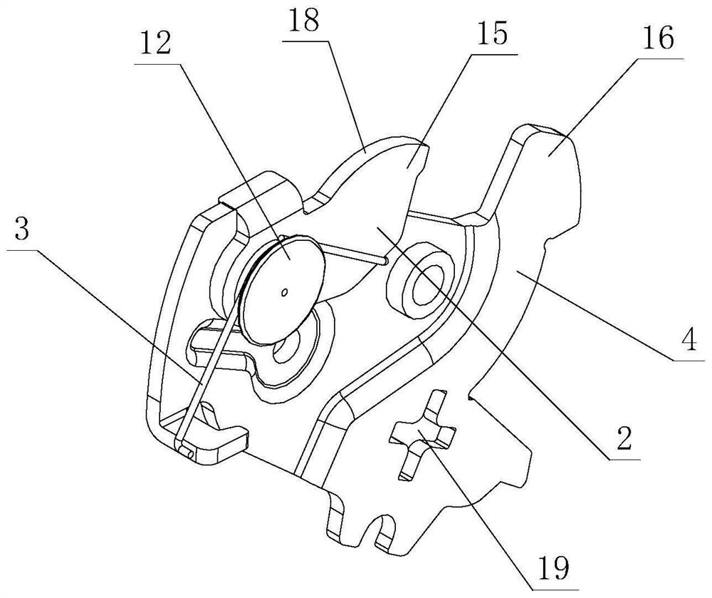
[0046] see Figure 1-Figure 17 , the lock-off and disassembly structure of the drawer panel includes a side panel 100, a drawer panel, a connecting element and a fixing element 1, the connecting element is provided with more than two, and is fixedly connected with the drawer panel respectively; the front end of the side panel 100 An assembly groove 200 is provided; the fixing element 1 is fixedly arranged on the assembly groove 200, and more than two lock-off elements for locking and separating the connecting elements are arranged on it; more than two lock-off elements are arranged relatively independently , and are provided with common elastic components.

[0047] Two or more lock-off elements are respectively elastically rotated or swayed on the fixed element 1 through elastic components, and are locked and separated from two or more connecting eleme...


PUM


Abstract

The invention relates to a locking and separating disassembly and assembly structure of a drawer panel. The structure comprises a fixing element and more than two connecting elements, and the fixing element is provided with more than two locking and separating elements; the more than two locking and separating elements are relatively independently arranged, and common elastic assemblies are arranged among the locking and separating elements; the more than two locking and separating elements elastically rotate or swing on the fixing element through the elastic components respectively, and are locked and separated from the more than two connecting elements respectively during rotation or swing so that the more than two connecting elements are disassembled and assembled on the fixing element; a movable part is arranged on one locking and separating element; the movable part moves on the locking and separating element in a limiting manner; and one connecting element acts on the movable part when sliding relative to the fixing element, drives the corresponding locking and separating element to elastically rotate or swing on the fixing element and is in locking fit with the connecting element. The drawer panel can be locked and detached conveniently, the use experience of a user is improved, and meanwhile the structure is simple and reasonable.

Description

technical field [0001] The invention relates to a lock-off and disassembly structure for a drawer panel. Background technique [0002] Chinese Patent Document No. CN103584524B discloses a locking and separating mechanism for a drawer panel on August 17, 2016. It includes an adjustment seat and an adjustment box arranged in the side panel of the drawer. The drawer panel is connected to the drawer panel through more than two connectors. The adjustment seat or the adjustment box body are connected, wherein the adjustment box body is set on the adjustment seat, the adjustment seat or the adjustment box body is provided with a locking device, and the locking device is provided with a push-out device with an automatic reset function, through the tool It acts on the action part of the push-out device, and drives the swing rod of the locking device to move to realize the disassembly and separation of the connecting piece and the locking device; the push-out device realizes automatic...

Claims


Application Information

Patent Timeline
IPC IPC(8): A47B88/90A47B88/944A47B88/95
CPCA47B88/90A47B88/944A47B88/95A47B2088/954
Inventor 伍志勇
Owner GUANGDONG DTC HARDWARE PRECISION MFG CO LTD
Why Eureka
Try Eureka