Slipring housing with bayonet lock
a technology of slipring and bayonet lock, which is applied in the direction of coupling device connection, current collector, electrical apparatus, etc., can solve the problems of large number of screws to be removed, and the disassembly is only possible with extremely high efforts, so as to reduce the cost or mass or inertia of the slipring
- Summary
- Abstract
- Description
- Claims
- Application Information
AI Technical Summary
Benefits of technology
Problems solved by technology
Method used
Image
Examples
first embodiment
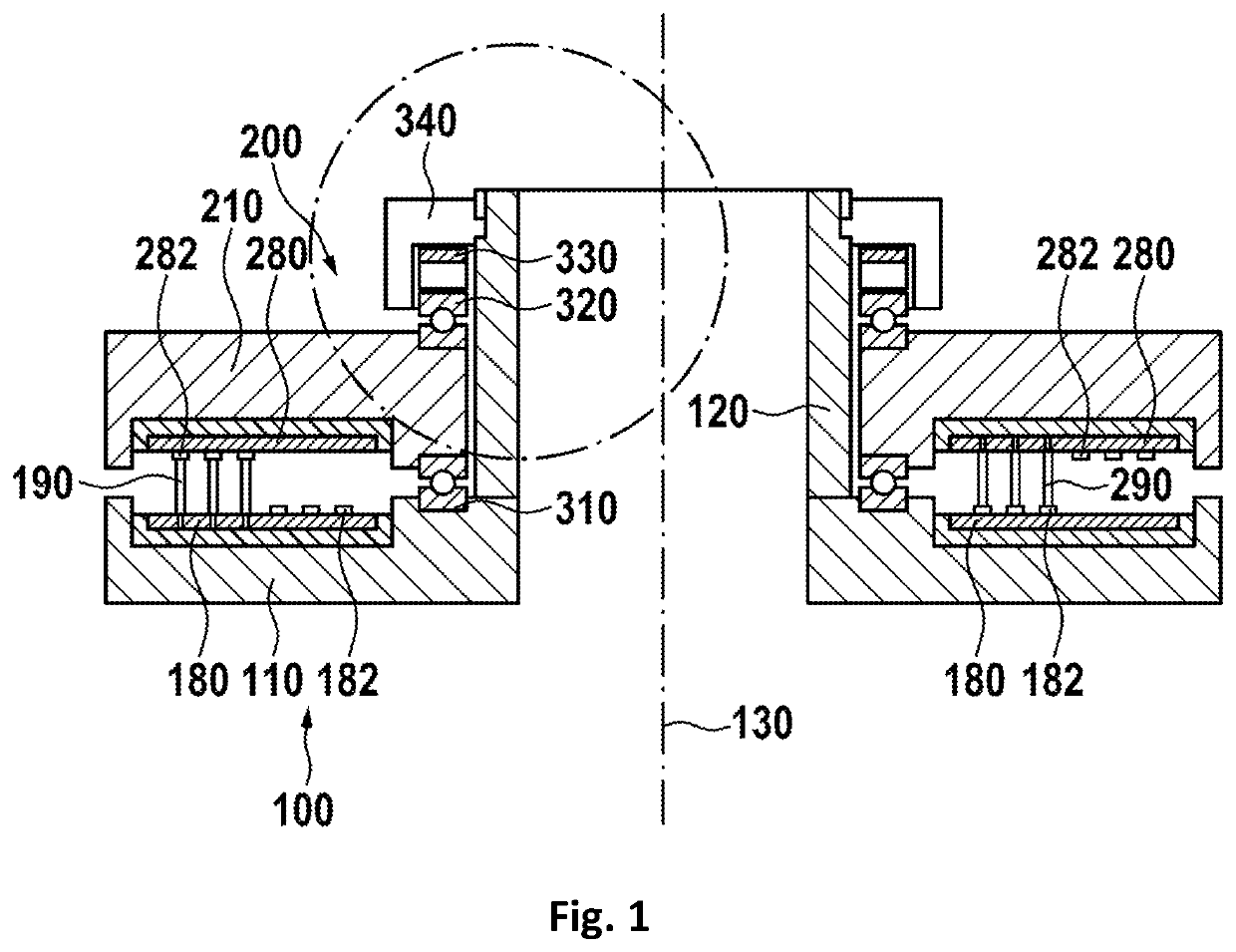
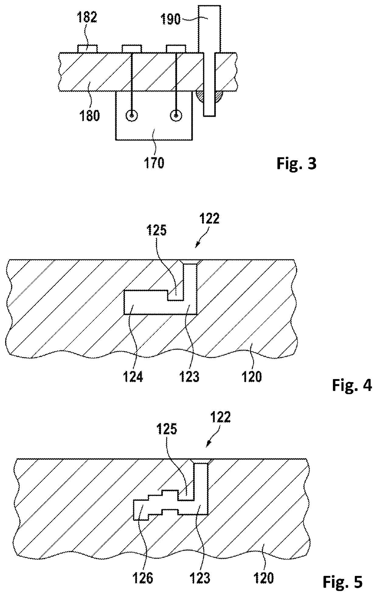
[0040]In FIG. 1, a slipring device is shown. The slipring device basically includes a first part 100 and a second part 200, which are rotatable against each other about a center axis 130. The first part 100 has a first housing 110 which holds a first printed circuit board (PCB) 180. This PCB may hold at least one first sliding track 182 and / or at least one contact brush 190.
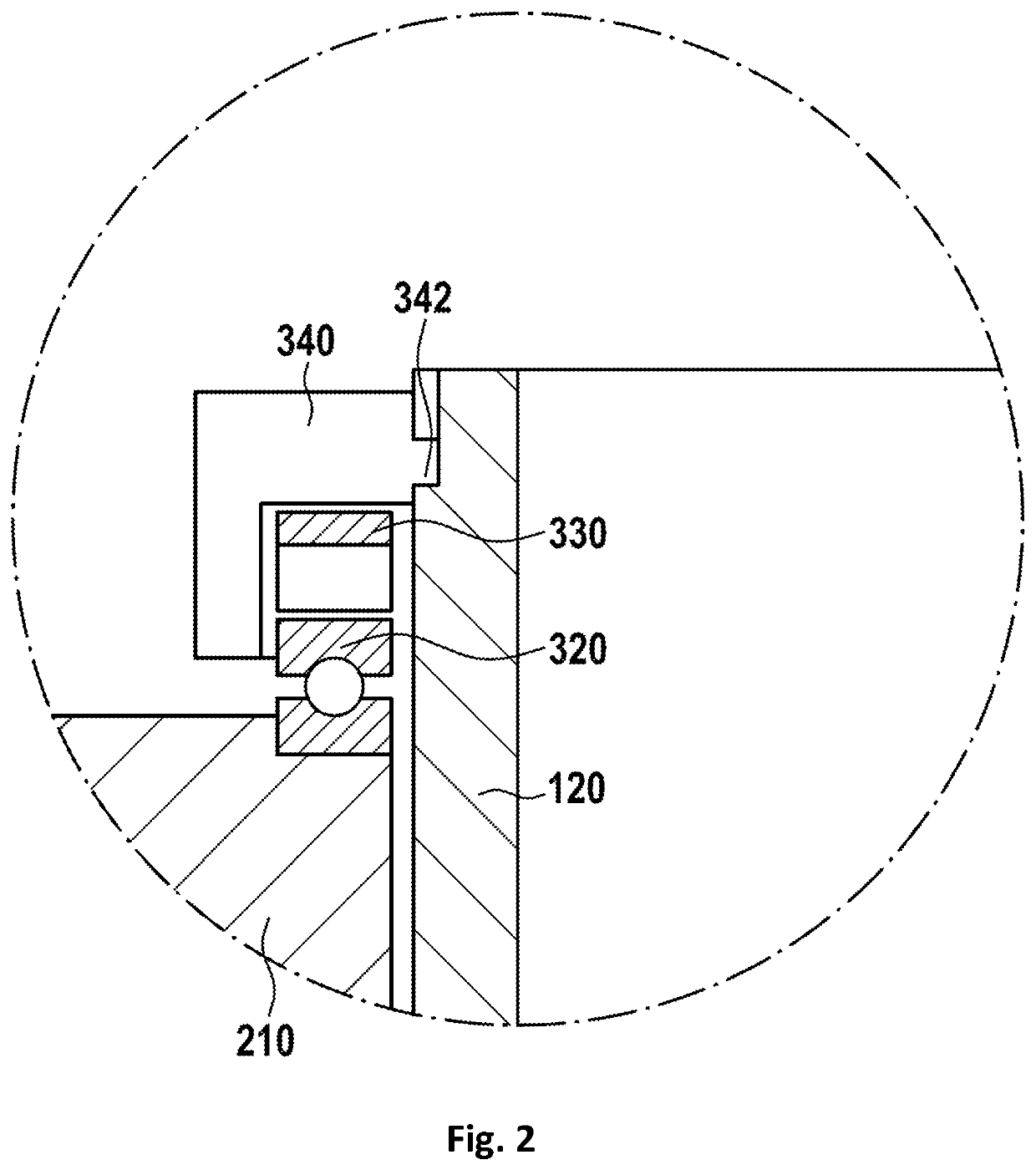
[0041]The second part 200 has a second housing 210 with a second PCB 280. The second PCB 280 may have at least one second contact brush 290 and at least one second sliding track 282. The sliding tracks and brushes are arranged such that a sliding track of the first PCB interfaces with a sliding brush of the second PCB, and vice versa to accomplish an electrical contact. Between the first housing 110 and the second housing 210 is at least a first bearing 310 which provides mechanical support and allows rotation of the second housing against the first housing. There may be at least a second bearing 320. The first h...
second embodiment
[0047]In FIG. 6, a slipring device is shown. The slipring device is similar to the slipring device of FIG. 1, but has different bearings. Here, instead of ball bearings, slide bearings, also called friction bearings are used. Such bearings have surfaces sliding against each other. In this embodiment, the ball bearings are replaced by a first slide bearing 410 and a second slide bearing 420.
[0048]FIG. 7 shows a detail of the locking ring with bayonet lock and a slide bearing. This is a detail of the previous figure.
third embodiment
[0049]FIG. 8 shows a slipring device. Here, no discrete slide bearings are used as in the previous embodiment. Instead, the second housing 210 may be sliding within first housing 110 and hollow shaft 120. The first housing 110 and the hollow shaft 120 may also be one part. There may be a bearing gap 510 between the second housing 210 slidably against first housing 110 and hollow shaft 120. There may be a lubricant in the bearing gap.
[0050]FIG. 9 shows a detail of the locking ring of the previous embodiment. There may be a counter bearing 520 to hold the second housing 210 in place. This counter bearing may also be part of the locking ring.
[0051]In FIG. 10, a further embodiment of a slipring device is shown. The slipring device is similar to the slipring device of FIG. 1, but has only one bearing, which may be a ball bearing.
[0052]FIG. 11 shows a detail of the locking ring of the previous embodiment.
PUM
 Abstract
Description
Claims
Application Information
 - R&D
- Intellectual Property
- Life Sciences
- Materials
- Tech Scout
- Unparalleled Data Quality
- Higher Quality Content
- 60% Fewer Hallucinations
Browse by: Latest US Patents, China's latest patents, Technical Efficacy Thesaurus, Application Domain, Technology Topic, Popular Technical Reports.
© 2025 PatSnap. All rights reserved.Legal|Privacy policy|Modern Slavery Act Transparency Statement|Sitemap|About US| Contact US: help@patsnap.com


