
Tunneling mechanism suitable for shield tunneling machine head

A shield machine and machine head technology, applied in mining equipment, earthwork drilling, tunnels, etc., can solve the problems of reducing the speed of excavation, large contact area, and affecting the speed of construction, so as to improve efficiency, improve fluidity, The effect of improving speed and work efficiency

Inactive Publication Date: 2021-11-05
长春市六石科技有限公司
View PDF0 Cites 0 Cited by
  • Summary
  • Abstract
  • Description
  • Claims
  • Application Information

AI Technical Summary

Problems solved by technology

[0003] The existing shield machines are basically a cylindrical steel component that excavates the soil while advancing along the tunnel axis, but the contact area between the cylindrical steel component and the soil is too large, which will reduce the speed of excavation , thus affecting the speed of construction

Method used


Image

  • Tunneling mechanism suitable for shield tunneling machine head
  • Tunneling mechanism suitable for shield tunneling machine head
  • Tunneling mechanism suitable for shield tunneling machine head

Examples


Embodiment Construction

[0027] The following will clearly and completely describe the technical solutions in the embodiments of the present invention with reference to the accompanying drawings in the embodiments of the present invention. Obviously, the described embodiments are only some, not all, embodiments of the present invention. Based on the embodiments of the present invention, all other embodiments obtained by persons of ordinary skill in the art without making creative efforts belong to the protection scope of the present invention.

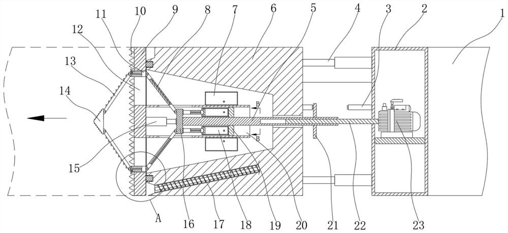
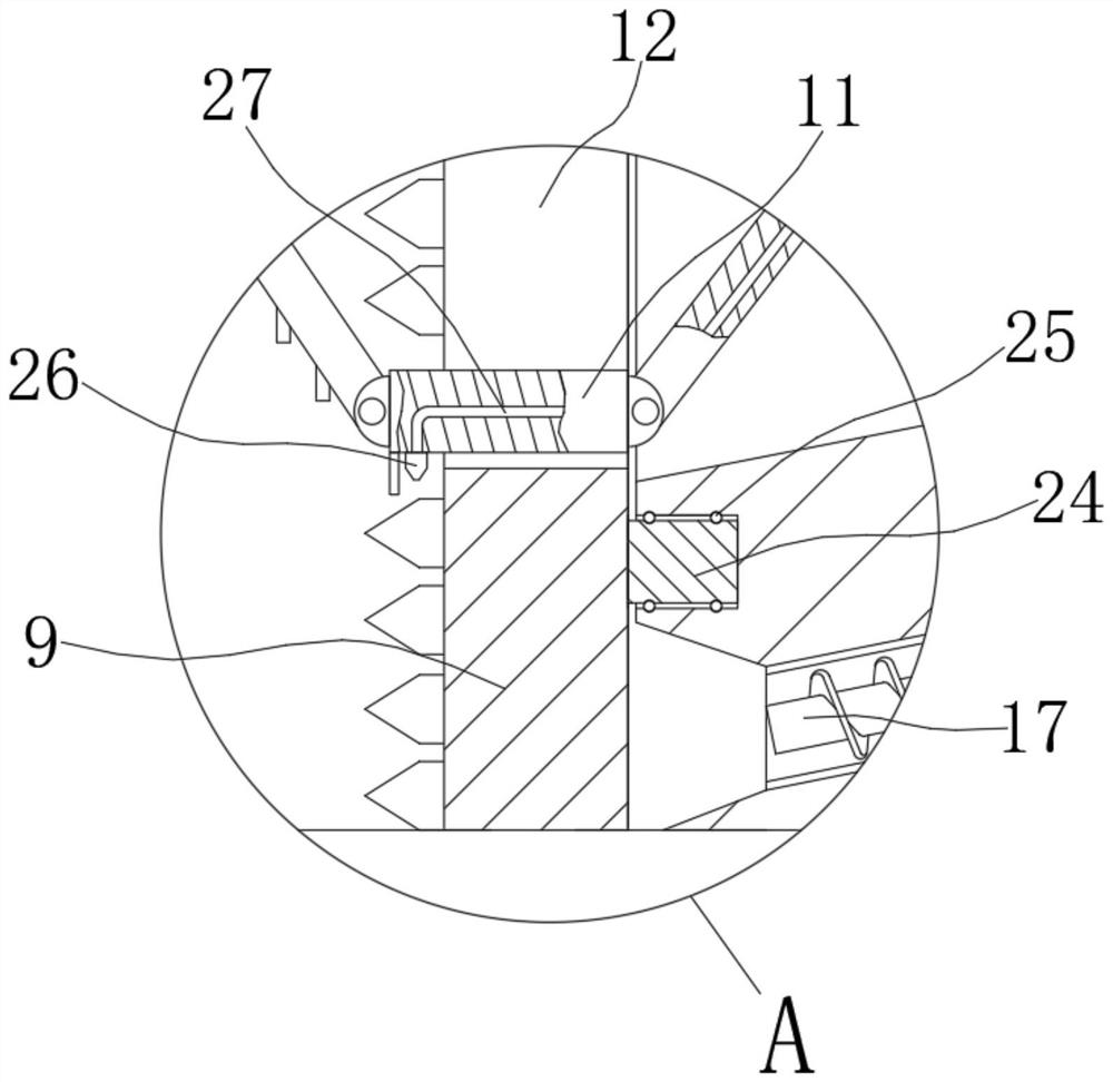
[0028] see Figure 1 to Figure 5 , the present invention provides a technical solution: a tunneling mechanism suitable for the head of a shield machine, including a shield machine body 1 capable of intermittent feeding, the head of the shield machine body 1 is fixed with a connection group 2, the connection group 2 The outer wall away from the shield machine body 1 is provided with a driving mechanism for forward driving.

[0029] The driving mechanism includ...


PUM


Abstract

The invention discloses a tunneling mechanism suitable for a shield tunneling machine head. The tunneling mechanism comprises a shield tunneling machine body capable of achieving intermittent feeding, a connecting set is fixed to the machine head of the shield tunneling machine body, the tunneling mechanism used for tunneling forwards is arranged on the outer wall, away from the connecting set, of the shield tunneling machine body, and the tunneling mechanism comprises a tunneling head. The tunneling head is arranged on the side, away from the shield tunneling machine body, of the connecting set and fixedly connected with the outer wall of the connecting set through a first hydraulic cylinder, a cutter head is rotationally installed on the outer wall, away from the connecting set, of the tunneling head, a plurality of cutters are installed on the outer wall of the cutter head, and a plurality of sliding grooves are formed in the outer wall of the cutter head. The multiple sliding grooves are distributed in a circumferential array mode, and a sliding block is installed on the inner wall of each sliding groove in a sliding mode. According to the tunneling mechanism suitable for the shield tunneling machine head, through cooperation of the structures, the contact area of the cutter head and soil can be reduced during tunneling every time, and then the tunneling speed and the working efficiency can be improved.

Description

technical field [0001] The invention relates to the technical field of shield machines, in particular to a tunneling mechanism suitable for the head of a shield machine. Background technique [0002] A shield machine is a tunnel boring machine that uses the shield method. The construction method of the shield is that the tunnel boring machine constructs the shield of the tunnel while excavating, which refers to the supporting segment. It is different from the open construction method. Usually, the tunnel boring machine used for soft ground is called a narrow shield machine. . [0003] The existing shield machines are basically a cylindrical steel component that excavates the soil while advancing along the tunnel axis, but the contact area between the cylindrical steel component and the soil is too large, which will reduce the speed of excavation , thereby affecting the speed of construction. [0004] In view of this, the present invention proposes a tunneling mechanism su...

Claims


Application Information

Patent Timeline
IPC IPC(8): E21D9/08E21D9/12
CPCE21D9/08E21D9/124
Inventor 宣彩梅
Owner 长春市六石科技有限公司
Learn More