
Air conditioner

A technology of an air conditioner and a shunt, which is applied in the field of air conditioners and can solve the problem of uneven distribution of refrigerants

Pending Publication Date: 2021-11-02
QINGDAO HISENSE HITACHI AIR CONDITIONING SYST
View PDF5 Cites 3 Cited by
  • Summary
  • Abstract
  • Description
  • Claims
  • Application Information

AI Technical Summary

Problems solved by technology

[0007] The invention provides an air conditioner, which can solve the problem that the gas-liquid two-phase refrigerant in the prior art air-conditioner is prone to gas-liquid phase separation in the manifold of the multi-flat tube parallel flow heat exchanger, resulting in uneven distribution of the refrigerant The problem

Method used


Image

  • Air conditioner
  • Air conditioner
  • Air conditioner

Examples


Embodiment 1

[0068] refer to Figure 4 to Figure 6 , an air conditioner in this embodiment includes a multi-flat tube parallel flow heat exchanger 10, and the multi-flat tube parallel flow heat exchanger 10 includes a plurality of flat tubes 100 and is used to evenly distribute the gas-liquid two-phase refrigerant to multiple Of course, the flow divider 200 in the flat tube 100 also includes fins 300 .

[0069] A plurality of flat tubes 100 are arranged at intervals up and down along the height direction of the multi-flat tube parallel flow heat exchanger 10 , and the distance between two vertically adjacent flat tubes 100 is 10-18mm. A plurality of micro-channels for circulating refrigerant are formed in the flat tube 100, and the flat tube 100 is penetrated in the fin 300, and the flow direction of the air flowing through the fin 300 is mutually related to the flow direction of the refrigerant flowing through the flat tube 100. Vertically, the heat / cold released by the refrigerant in th...

Embodiment 2

[0098] refer to Figure 14 to Figure 20 , in this embodiment, for the convenience of description, the side of the flat flow channel 211 that communicates with the refrigerant inlet 220 is defined as the first side 211A in the thickness direction of the flat flow channel 211, and the other side that communicates with the refrigerant outlet 230 is the flat side. The second side surface 211B in the thickness direction of the channel 211 .

[0099] The difference from Embodiment 1 is that along the extending direction of the flat channel 211 in this embodiment, the first side 211A in the thickness direction consists of the first sub-side 211A1 located on one side of the refrigerant inlet 220 and the first sub-side 211A1 located on the other side of the refrigerant inlet 220 . The first sub-side 211A1 and the second sub-side 211A2 are both inclined to the side where the refrigerant inlet 220 is located.

[0100]The reason for this design is that when the high-speed gas-liquid two-...


PUM


Abstract

The invention provides an air conditioner. The air conditioner can solve the problem that in the prior art, gas-liquid two-phase refrigerants of an air conditioner are prone to gas-liquid separation in a collecting pipe of a multi-flat-pipe parallel flow heat exchanger, and consequently the refrigerants are distributed unevenly. The air conditioner comprises a multi-flat-tube parallel flow heat exchanger, the multi-flat-tube parallel flow heat exchanger comprises a plurality of flat tubes and a flow divider used for evenly distributing gas-liquid two-phase refrigerants into the flat tubes, the flow divider comprises a flow divider body, a refrigerant inlet and a plurality of refrigerant outlets, a flat flow channel is formed in the flow divider body, the refrigerant inlet communicates with the flat flow channel, and the multiple refrigerant outlets communicate with the flat flow channel and are distributed in the extending direction of the flat flow channel. According to the air conditioner, by arranging the flow divider, the gas-liquid two-phase refrigerants can be evenly distributed into the multiple flat tubes, and therefore the performance of a micro-channel heat exchanger is improved.

Description

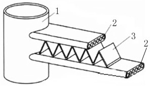
technical field [0001] The invention relates to the technical field of air conditioners, in particular to an air conditioner. Background technique [0002] In order to reduce the production cost of air-conditioning heat exchangers, some manufacturers have begun to produce all-aluminum heat exchangers. Compared with traditional finned tube heat exchangers, because copper tubes are no longer used, the cost of heat exchanger materials The reduction can reach 40%. The micro-channel parallel flow heat exchanger is a common all-aluminum heat exchanger. This heat exchanger arranges multiple flat tubes in the vertical direction. The multiple flat tubes are directly connected by headers. Fins are used to enhance heat exchange with air, common microchannel heat exchangers such as figure 1 As shown, it includes header 1, flat tube 2 and fin 3. [0003] Since the heat exchanger of a commercial air conditioner is very large, the height generally exceeds 800mm. According to statistics,...

Claims


Application Information

Patent Timeline
Patent Type & Authority Applications(China)
IPC IPC(8): F24F1/0063F24F1/0068F24F13/30
CPCF24F1/0063F24F1/0068F24F13/30
Inventor 赵东方李晓宇石丽华曹法立刘晓蕾
Owner QINGDAO HISENSE HITACHI AIR CONDITIONING SYST
Learn More