
Bladeless fan

A bladeless fan and windshield technology, which is applied to parts of pumping devices for elastic fluids, non-variable pumps, pump devices, etc., can solve the problems of insufficient decorative properties, large space occupation, and unnatural wind feeling, etc. question

Pending Publication Date: 2021-11-02
ZHONGSHAN ODEER ELECTRONICS LIGHTING
View PDF0 Cites 0 Cited by
  • Summary
  • Abstract
  • Description
  • Claims
  • Application Information

AI Technical Summary

Problems solved by technology

However, the existing fans on the market are all with visible blades. Vertical or ceiling fans take up a lot of space overall, the air outlet range is not large enough, the wind feeling is not natural enough, and the decorative attributes are not enough.
While a small number of fans can achieve a bladeless fan structure, but none of them have the function of swinging the wind

Method used


Image

  • Bladeless fan
  • Bladeless fan
  • Bladeless fan

Examples


Embodiment 1

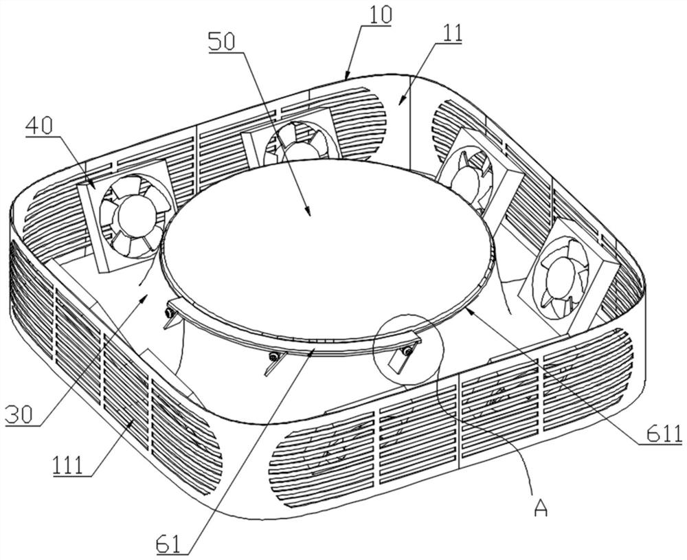
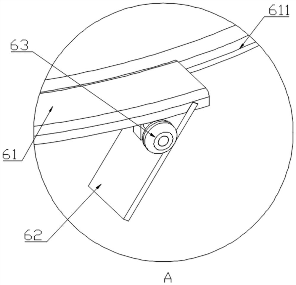
[0040] see Figure 1 to Figure 3 as well as Figure 6 , a bladeless fan in this embodiment, including a bottom case 10, an upper cover 20, an air duct member 30, several sets of fan assemblies 40, a protective cover 50, and a wind swing mechanism;

[0041] Specifically, the bottom case 10 is provided with a receiving groove 11, and the side wall of the receiving groove 11 is provided with an air inlet 111;

[0042] More specifically, the air inlets 111 are evenly distributed circumferentially around the side wall of the accommodation groove 11; the bottom shell 10 is in a concave shape as a whole, and the concave position forms the accommodation groove 11, and the side wall of the accommodation groove 11 is thin-walled. Moreover, the housing and the receiving groove 11 are in a rectangular shape as a whole.

[0043] Specifically, the upper cover 20 is arranged at the opening of the accommodating groove 11; the bottom case 10 and the upper cover 20 can preferably be connected...

Embodiment 2

[0059] see Figure 4 to Figure 6 , a bladeless fan of this embodiment, the difference between Embodiment 2 and Embodiment 1 is that the structure of the wind swing mechanism is different. The structure and working principle of the wind swing mechanism in Embodiment 2 are described in detail below:

[0060] The wind swing mechanism includes an annular grille 64 and a drive assembly; the annular grille 64 is rotatably arranged on the top of the air duct member 30 and covers the air outlet channel 31, and the annular grille 64 is provided with a plurality of mutual Parallel elongated through-holes 21; the annular grille 64 can be respectively provided with an annular track and an annular chute on the top of the air duct member 30 and connected with an annular track to realize the rotational connection of the two, and realize the rotation of the other. The connection structure belongs to the prior art, and will not be repeated here;

[0061] The driving assembly drives the annula...

Embodiment 3

[0066] see Figure 7 to Figure 9 , a bladeless fan in this embodiment, including a bottom case 10, an upper cover 20, an air duct member 30, several sets of fan assemblies 40, a protective cover 50, and a wind swing mechanism;

[0067] Specifically, the bottom case 10 is provided with a receiving groove 11, and the side wall of the receiving groove 11 is provided with an air inlet 111;

[0068] More specifically, the air inlets 111 are evenly distributed circumferentially around the side wall of the accommodation groove 11; the bottom shell 10 is in a concave shape as a whole, and the concave position forms the accommodation groove 11, and the side wall of the accommodation groove 11 is thin-walled. Moreover, the housing and the receiving groove 11 are in a rectangular shape as a whole.

[0069] Specifically, the upper cover 20 is arranged at the opening of the accommodating groove 11; the bottom case 10 and the upper cover 20 can preferably be connected by a buckle;

[0070...


PUM


Abstract

The invention relates to a bladeless fan which comprises a bottom shell, an upper cover, an air duct piece, a plurality of fan assemblies and an air swinging mechanism; the bottom shell is provided with an accommodating groove, and an air inlet is formed in the side wall of the accommodating groove; the upper cover is arranged at the opening of the accommodating groove; the upper cover is provided with a through hole; the air duct piece is arranged in the accommodating groove and located on the inner side of the air inlet; an air outlet channel is formed between the outer side edge of the top end of the air duct piece and the inner edge of the through hole; the fan assemblies are arranged between the air inlet and the air duct piece; and the air swinging mechanism is used for changing the air direction of the air outlet channel. According to the bladeless fan, the fan assemblies are hidden in the bottom shell, the air direction is changed through the air duct piece, air enters the bottom shell from the side face of the bottom shell and then is exhausted from the air outlet channel in the position of the upper cover, the effect that the air enters from the side face and exits from the front face is achieved, the hiding effect of fan blades is achieved, the air feeling is natural, and the hidden fan decoration attribute and the safety attribute are higher; and by arranging an air swinging assembly, air outlet change of the air outlet channel can be achieved, and the practicability and functionality of the bladeless fan are improved.

Description

technical field [0001] The invention relates to the technical field of fans, in particular to a bladeless fan. Background technique [0002] Fans have become an indispensable product in people's daily life, and are widely used in homes, offices, shops, outdoors and other places. However, the existing fans on the market are all with visible blades. Vertical or ceiling fans take up a lot of space as a whole, the air outlet range is not large enough, the wind feeling is not natural enough, and the decorative attributes are not enough. While a small number of fans can achieve a bladeless fan structure, but none of them have the function of swinging the wind. Contents of the invention [0003] Based on this, the object of the present invention is to overcome the shortcomings and deficiencies in the prior art and provide a bladeless fan. [0004] A bladeless fan, including a bottom case, an upper cover, an air duct piece, several fan components, and a wind swing mechanism; ...

Claims


Application Information

Patent Timeline
Patent Type & Authority Applications(China)
IPC IPC(8): F04D25/08F04D29/40F04D29/60
CPCF04D25/08F04D29/403F04D29/601
Inventor 赵伟
Owner ZHONGSHAN ODEER ELECTRONICS LIGHTING
Learn More