Tapping embroidery device and taping embroidery feeding control method

A tape embroidery and material feeding technology, which is applied in the tape embroidery device and the field of tape embroidery feeding control, can solve the problems of embroidery drawing deformation, large mechanical pulling force of the embroidery frame, bad embroidery, etc., and achieve the effect of simple control method

Active Publication Date: 2021-11-02
浙江镨美科智能刺绣设备有限公司
View PDF8 Cites 1 Cited by
  • Summary
  • Abstract
  • Description
  • Claims
  • Application Information

AI Technical Summary

Problems solved by technology

[0004] Aiming at the problems existing in the prior art, the present invention proposes a tape embroidery device and a tape embroidery feeding control method, which can solve the large mechanical pulling force when the embroidery frame moves due to the increase in the size of the material tray, and then cause Deformation of the embroidery, resulting in bad embroidery

Method used


Image

  • Tapping embroidery device and taping embroidery feeding control method
  • Tapping embroidery device and taping embroidery feeding control method
  • Tapping embroidery device and taping embroidery feeding control method

Examples


Embodiment approach

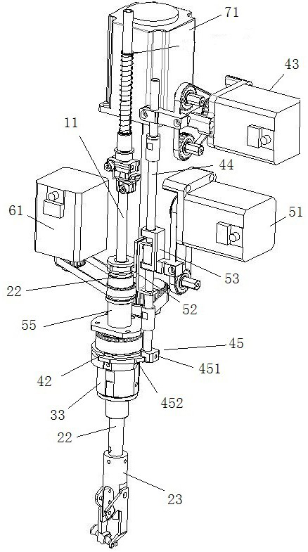
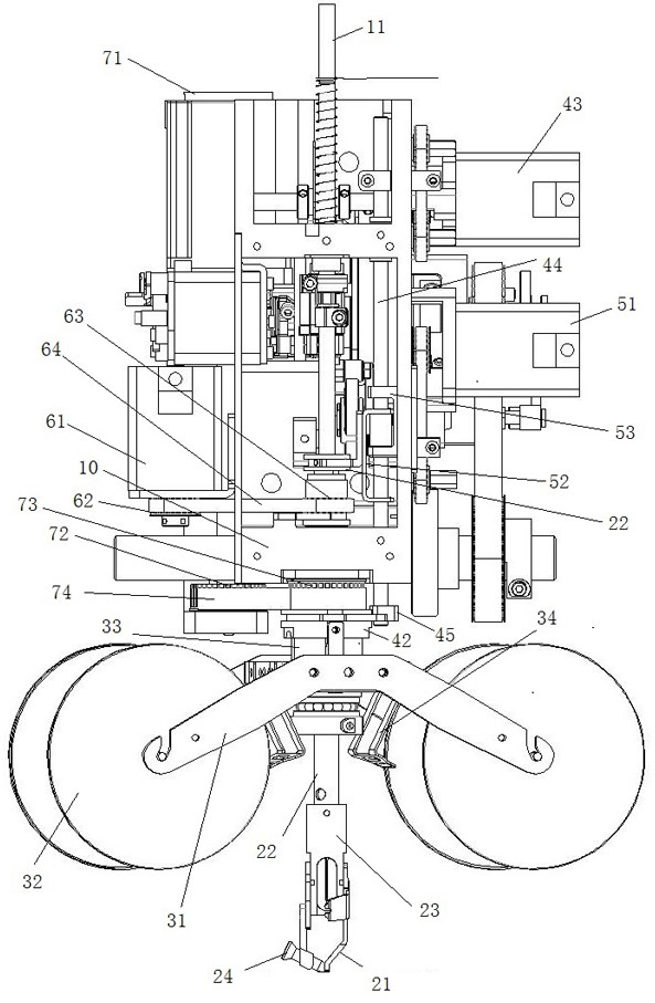
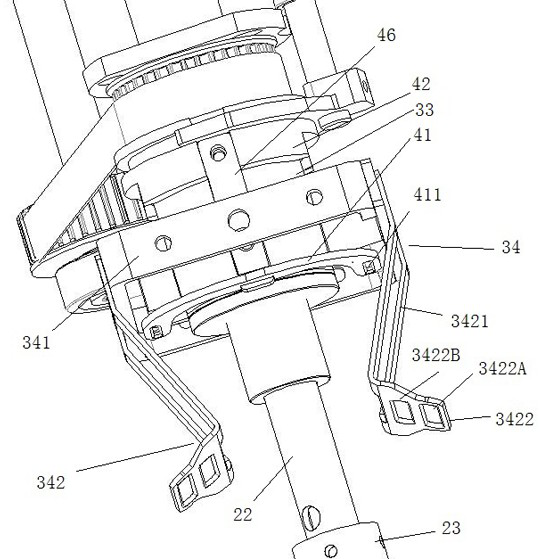
[0051] figure 1 , 2 The specific structure of the conveying frame 34 is shown, and the conveying frame 342 includes a first slant plate 3421 inclined downward from the side of the material tray 32 to the side of the presser foot sleeve 22, and from the side of the presser foot sleeve 22 to the side of the material tray 32. The second sloping plate 3422 that slopes sideways downward. One end of the first slanting plate 3421 is connected to the general installation frame 341 , and the other end is connected to the second slanting plate 3422 . The second sloping plate 3422 is provided with conveying holes. The feeding rack adopts lifting mode, its structure is as follows: figure 2 As shown in , the feeding frame is an annular structure with an opening, which is arranged around the feeding sleeve 42 . The feeding frame 41 is fixedly connected to the feeding sleeve through a vertical feeding connector 46, and the feeding frame is horizontally arranged relative to the needle pl...


PUM


Abstract

The invention discloses a taping embroidery device and a taping embroidery feeding control method, and belongs to the technical field of embroidery machines. The taping embroidery device comprises a machine shell, a presser foot part, a tray part and a rotary driving mechanism; the presser foot sleeve vertically penetrates through the machine shell, a fixing sleeve and a shaft sleeve sequentially sleeve the presser foot sleeve, and the fixing sleeve is fixed to the machine shell; the rotary driving mechanism drives a tray rack to rotate; the taping embroidery device further comprises a feeding frame and a feeding lifting driving mechanism; a feeding sleeve sleeves the shaft sleeve, and the feeding frame is installed on the feeding sleeve; the feeding lifting driving mechanism is used for driving the feeding frame to ascend or descend in the vertical direction or swing transversely; and the rotary driving mechanism is used for driving the feeding frame to rotate. The taping embroidery feeding control method is realized based on the taping embroidery device, and comprises the following steps that firstly a machine needle is controlled to move to lock a rope or a belt, then the feeding frame is controlled to lift, then the machine needle is controlled to pull out, a tabouret is controlled to move, the feeding frame is controlled to descend, and the machine needle is controlled to move again until the taping embroidery operation is finished. According to the taping embroidery device and the taping embroidery feeding control method, the problem of poor embroidery caused by pulling deformation of the embroidery is solved.

Description

technical field [0001] The invention belongs to the technical field of embroidery machines, and in particular relates to a tape embroidery device and a tape embroidery feeding control method. Background technique [0002] The taping embroidery device is used to embroider tapes and / or ropes and other ribbons. The tape embroidery device is generally composed of a casing, a drive spindle, a needle bar, a feeding part, a presser foot, and a thread take-up rod. In order to improve the continuous working time of tape embroidery, the existing feeding part adopts large-size material trays to carry large-capacity tape materials. During tape embroidery operation, the needle is inserted into the embroidery material, and the upper thread locks the rope or belt on the embroidery material. At this time, when the embroidery frame is moved, the embroidery frame will drive the rope / belt to move. When the size of the material reel increases, the rope or tape will be mechanically pulled out ...

Claims


Application Information

Patent Timeline
Patent Type & Authority Applications(China)
IPC IPC(8): D05C7/08D05C11/08
CPCD05C7/08D05C11/08
Inventor 陈天龙方狄永
Owner 浙江镨美科智能刺绣设备有限公司
Why Eureka
Try Eureka