
Model injection molding device for manufacturing electronic components

A technology for electronic components and models, applied in the field of model injection molding devices for electronic component manufacturing, can solve problems such as affecting the quality of injection molding, affecting the quality of injection molding, and easily adhering to dust, etc.

Pending Publication Date: 2021-11-02
阳喜发
View PDF0 Cites 2 Cited by
  • Summary
  • Abstract
  • Description
  • Claims
  • Application Information

AI Technical Summary

Problems solved by technology

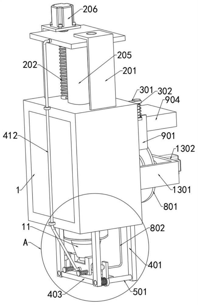
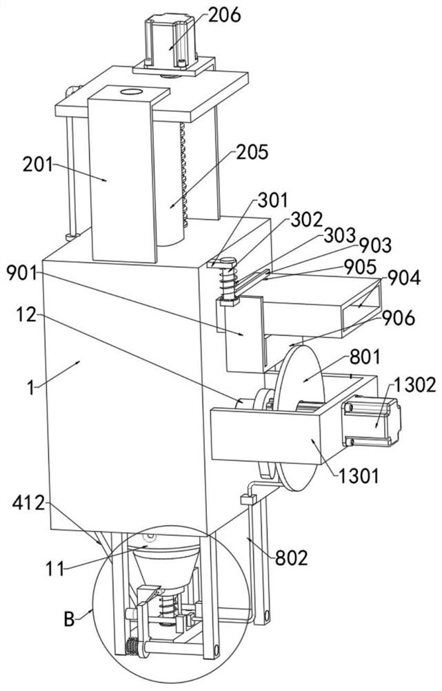
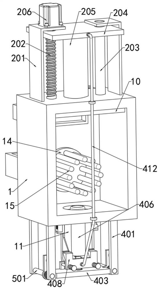
[0004] The present invention aims at the technical problems existing in the prior art, and provides a model injection molding device for the manufacture of electronic components to solve the problem that during the existing injection molding process, the raw materials in the mold head are in contact with the outside air, and impurities such as dust are easily adhered, thereby It affects the quality of injection molding, and the raw materials in the mold head are prone to solidification, and the solidified raw materials will enter the mold, thereby affecting the quality of injection molding, and even causing the problem of blockage of the injection molding head

Method used


Image

  • Model injection molding device for manufacturing electronic components
  • Model injection molding device for manufacturing electronic components
  • Model injection molding device for manufacturing electronic components

Examples


Embodiment Construction

[0040] The principles and features of the present invention are described below in conjunction with the accompanying drawings, and the examples given are only used to explain the present invention, and are not intended to limit the scope of the present invention.

[0041] Electronic components are components of electronic components and small electrical machines and instruments. They are often composed of several parts and can be used in similar products; they often refer to certain parts in industries such as electrical appliances, radios, and instruments, such as capacitors and transistors. The general term for sub-components such as springs, hairsprings, and springs. After the electronic components are manufactured, they need to be assembled with plastic molds for use. During injection molding, the raw materials need to be melted first, and then added to the injection molding machine. The raw materials are poured into the mould.

[0042] After in-depth investigation and res...


PUM


Abstract

The invention relates to the technical field of model injection molding, in particular to a model injection molding device for manufacturing electronic components. The model injection molding device for manufacturing the electronic components comprises a heating box and an injection molding head arranged at the bottom of the heating box, and a piston plate is slidably connected to the interior of the heating box and is driven by a first driving mechanism. According to the model injection molding device, compared with the prior art, the model injection molding device for manufacturing the electronic component has the beneficial effects that when injection molding is completed, raw materials remaining in the injection molding head can enter the heating box together, so that the situation that the raw materials in the injection molding head block the injection molding head or the raw materials enter an injection molding product after being condensed is avoided, meanwhile, the injection molding head can be sealed, external dust and other impurities are prevented from entering, meanwhile, the molten raw materials remaining in the injection molding head are completely pushed into the heating box, the injection molding quality is guaranteed, automatic detection and automatic quantitative adding can be conducted on the raw materials in the heating box, injection molding is more convenient, and the injection molding effect is guaranteed.

Description

technical field [0001] The invention relates to the technical field of mold injection molding, in particular to a mold injection molding device for manufacturing electronic components. Background technique [0002] Electronic components are components of electronic components and small electrical machines and instruments. They are often composed of several parts and can be used in similar products; they often refer to certain parts in industries such as electrical appliances, radios, and instruments, such as capacitors and transistors. The general term for sub-devices such as springs, hairsprings, and springs. [0003] After the electronic components are manufactured, they need to be assembled with plastic molds for use. During injection molding, the raw materials need to be melted first, and then added to the injection molding machine. Then, the molten raw materials are injected into the mold through the injection head. However, in the injection molding process In the proc...

Claims


Application Information

Patent Timeline
Patent Type & Authority Applications(China)
IPC IPC(8): B29C45/53B29C45/76B29C45/20B29C45/74
CPCB29C45/531B29C45/76B29C45/20B29C45/74B29C2945/76658B29C2045/202
Inventor 不公告发明人
Owner 阳喜发
Learn More