
PIN implantation equipment

A technology for implanting equipment and channels, which is applied in the direction of household components, household appliances, and other household appliances, etc., can solve problems affecting the efficiency of PIN needle implantation, and achieve the effect of improving efficiency

Pending Publication Date: 2021-11-02
优悠电子科技惠州市有限公司
View PDF5 Cites 0 Cited by
  • Summary
  • Abstract
  • Description
  • Claims
  • Application Information

AI Technical Summary

Problems solved by technology

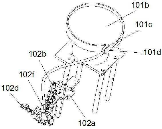
Due to the lack of a corresponding PIN needle sorting or PIN needle screening structure at the connection between the vibration plate and the Teflon tube, the PIN needles pre-placed in the vibration plate are easy to gather at the vibration plate and the Teflon tube at one time. The junction of the above-mentioned Teflon tube, so that the PIN needle blocks the feed port of the Teflon tube; further, because the Teflon tube is directly connected with the PIN ejection mechanism, in order to make the PIN needle in the The Teflon tube slides smoothly, and the diameter of the Teflon tube must be much larger than the diameter of the PIN needle. Therefore, it is easy to cause multiple PIN needles to enter the PIN ejection mechanism at one time, thereby causing the PIN needles to be ejected out of order. Or too many PIN needles are implanted in the positioning jig at one time, which affects the implantation efficiency of the PIN needles

Method used


Image

  • PIN implantation equipment
  • PIN implantation equipment
  • PIN implantation equipment

Examples


Embodiment Construction

[0020] In order to make the above objects, features and advantages of the present invention more comprehensible, specific implementations of the present invention will be described in detail below in conjunction with the accompanying drawings. In the following description, numerous specific details are set forth in order to provide a thorough understanding of the present invention. However, the present invention can be implemented in many other ways different from those described here, and those skilled in the art can make similar improvements without departing from the connotation of the present invention, so the present invention is not limited by the specific embodiments disclosed below.

[0021] In describing the present invention, it should be understood that the terms "center", "longitudinal", "transverse", "length", "width", "thickness", "upper", "lower", "front", " Back", "Left", "Right", "Vertical", "Horizontal", "Top", "Bottom", "Inner", "Outer", "Clockwise", "Counte...


PUM


Abstract

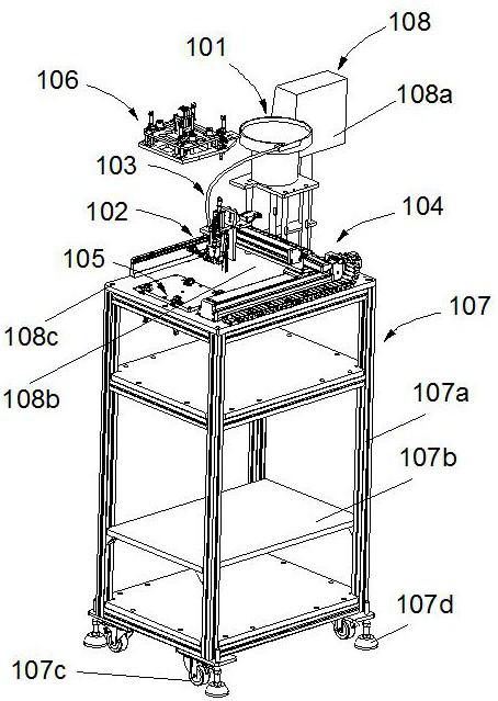
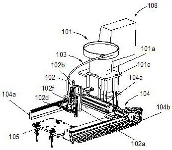
The invention discloses a PIN implantation device which is provided with a PIN temporary storage disc, a PIN pre-screening channel and a PIN sorting channel which are connected in sequence, so that to-be-implanted PIN materials which are placed in a PIN feeding vibration disc in advance can be sequentially gathered into the feeding end of the PIN pre-screening channel step by step from the PIN temporary storage disc, then the to-be-implanted PIN materials can be transferred into the PIN sorting channel from the discharging end of the PIN pre-screening channel one by one, and finally, the to-be-implanted PINs enter a PIN conveying pipe from an outlet of the PIN sorting channel one by one; and the defect that the to-be-implanted PINs block the PIN conveying pipe can be avoided through the step-by-step screening and discharging process. By means of the PIN implantation equipment, the efficiency of full-automatically implanting the PINs into injection molds is effectively improved.

Description

technical field [0001] The invention relates to the technical field of injection molding technology, in particular to a PIN needle implantation device. Background technique [0002] With the rapid development of electronic connectors, short, small, light and thin miniature electronic connectors have become the mainstream of competition in the electronic connector industry. The single straight PIN pin connector sockets on the market are widely used in automotive connectors Or connectors for smart wearable products. The structures of the connectors in the above different application fields vary greatly, but their core components are basically the same, namely: PIN pins, insulators and shells. The PIN needle is the core component of the connector, and the electrical signal between the connectors needs to be transmitted by the PIN needle, so the material of the PIN needle is generally copper, silver or steel and other similar metals, while the shell of the connector is more Fo...

Claims


Application Information

Patent Timeline
Patent Type & Authority Applications(China)
IPC IPC(8): B29C45/14B29L31/36
CPCB29C45/14008B29C2045/14868B29L2031/36
Inventor 周文基
Owner 优悠电子科技惠州市有限公司
Learn More