
Connector

A connector and contact surface technology, which is applied in the direction of connection, fixed connection, and parts of the connection device, can solve problems such as poor crosstalk, small shielding space, and poor anti-interference ability, so as to optimize the return path and facilitate processing and molding. The effect of improving the transmission capacity

Pending Publication Date: 2021-10-29
CHINA AVIATION OPTICAL-ELECTRICAL TECH CO LTD
View PDF0 Cites 0 Cited by
  • Summary
  • Abstract
  • Description
  • Claims
  • Application Information

AI Technical Summary

Problems solved by technology

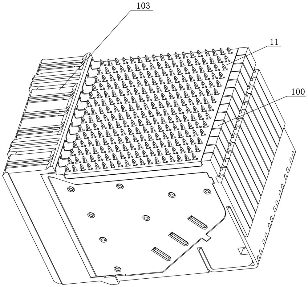
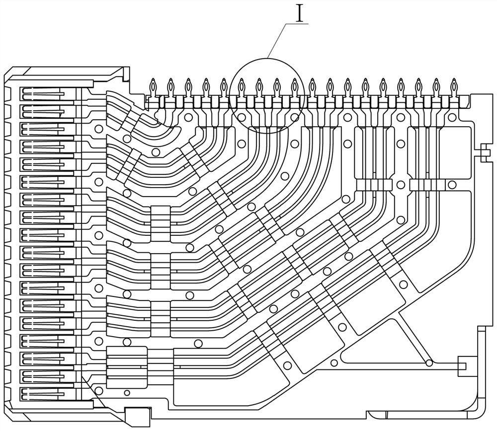
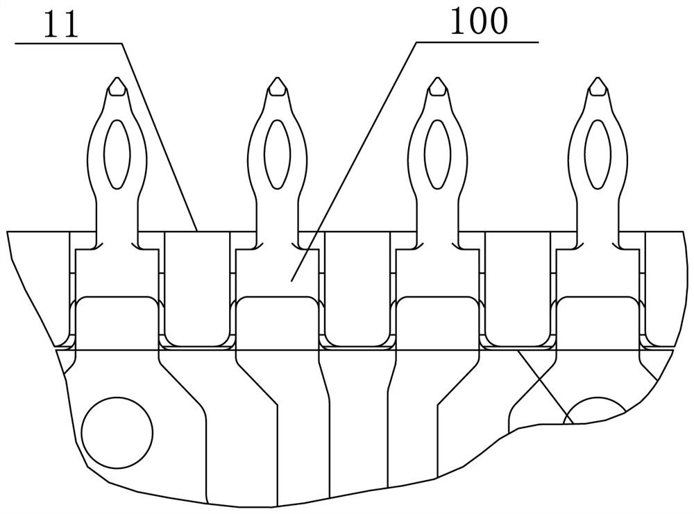
[0002] In the prior art, such as figure 1 As shown, the connector is composed of a terminal module and a buckle plate for limiting and facilitating the extension of the crimping end of the terminal module, such as figure 2 , image 3 , Figure 4 , Figure 5 , Image 6 As shown, the signal crimping end and the grounding crimping end of the terminal module of the connector are connected on the same plane, the shielding space is small, and the fit between the crimping end and the buckle plate is a gap fit, and there is no contact; Figure 7 As shown, and the daughter board is LCP, which is not conductive, has poor anti-interference ability and poor crosstalk

Method used


Image

  • Connector
  • Connector
  • Connector

Examples


Embodiment Construction

[0045] The preferred embodiments of the invention are given below in conjunction with the accompanying drawings to describe the technical solutions of the present invention in detail. Here, the present invention will be described in detail with reference to the accompanying drawings. It should be noted that the preferred implementation examples described here are only used to illustrate and explain the present invention, and are not used to limit or limit the present invention.

[0046] Such as Figure 8 As shown, a connector includes a terminal module 100, which constitutes the basic structure of the connector. The terminal module 100 can be fixed as a whole by adding a fixing piece 102. The middle part of the terminal module 100 is a terminal wiring 1001c, and the two ends are respectively The contact structure 1001a and the crimping end structure 1001b, the contact structure 1001a is installed with an insulator 103 for plugging with other connectors, and the crimping end s...


PUM


Abstract

The invention provides a connector and relates to the technical field of communication equipment comprising a terminal module, the terminal module comprises terminal sheets arranged side by side along the longitudinal direction, each terminal sheet comprises signal differential pairs and grounding terminals which are sequentially and alternately arranged along the transverse direction, and two ends of each terminal sheet are respectively a contact structure and a crimping end structure. The crimping end structure comprises signal differential pair crimping ends and grounding crimping ends which are sequentially and alternately arranged in the transverse direction, each signal differential pair crimping end comprises a pair of signal crimping ends, the middle part of each grounding crimping end is bent to form a grounding pin, and the unbent parts of the two sides of each grounding pin form convex blocks; the extension directions of the crimping ends of the signal differential pairs are arranged in a coplanar mode, the plane where the crimping ends of the signal differential pairs are located is a first plane, the plane where the adjacent grounding pins on the two transverse sides are located is a second plane, the plane where the convex blocks on the two sides of the grounding pins are located is a third plane, and the first plane and the second plane are parallel and not overlapped. The second plane and the third plane are parallel and not overlapped. According to the invention, the shielding space is increased, and the anti-interference capability of signals is improved.

Description

technical field [0001] The invention relates to the technical field of communication equipment, in particular to a connector. Background technique [0002] In the prior art, such as figure 1 As shown, the connector is composed of a terminal module and a buckle plate for limiting and facilitating the extension of the crimping end of the terminal module, such as figure 2 , image 3 , Figure 4 , Figure 5 , Image 6 As shown, the signal crimping end and the grounding crimping end of the terminal module of the connector are connected on the same plane, the shielding space is small, and the fit between the crimping end and the buckle plate is a gap fit, and there is no contact; Figure 7 As shown, and the daughter board is LCP, which is not conductive, has poor anti-interference ability and poor crosstalk. Contents of the invention [0003] In order to solve the above technical problems, the present invention provides a connector, which increases the shielding space and...

Claims


Application Information

Patent Timeline
IPC IPC(8): H01R13/652H01R13/655H01R13/02H01R13/6461H01R13/6581H01R13/6594H01R12/57H01R12/65
CPCH01R13/652H01R13/655H01R13/02H01R13/6581H01R13/6461H01R12/57H01R12/65H01R13/6594
Inventor 程喜乐许海轲关中杰鲁中原孙庆果
Owner CHINA AVIATION OPTICAL-ELECTRICAL TECH CO LTD
Learn More