
Vibration isolator based on hydraulic servo control

A technology of servo control and vibration isolator, which is applied in the field of vibration reduction and noise reduction, can solve the problems that the metal spring vibration isolator cannot satisfy, the vibration source excitation constant force component has a large variation range, and achieve the effect of ensuring support and avoiding damage

Pending Publication Date: 2021-10-29
CHINA SHIP DEV & DESIGN CENT
View PDF5 Cites 0 Cited by
  • Summary
  • Abstract
  • Description
  • Claims
  • Application Information

AI Technical Summary

Problems solved by technology

[0003] The technical problem to be solved by the present invention is to provide an isolator based on hydraulic servo control for the above-mentioned existing metal spring vibration isolators that cannot satisfy the use environment where the vibration source excitation constant force component has a large variation range and the vibration source displacement is limited. The vibrator, through the hydraulic servo control adaptive vibration source constant force, ensures that the displacement of the vibration source does not exceed the limit value, and realizes the vibration isolation function within the full load range

Method used


Image

  • Vibration isolator based on hydraulic servo control
  • Vibration isolator based on hydraulic servo control

Examples


Embodiment Construction

[0022] In order to have a clearer understanding of the technical features, purposes and effects of the present invention, the specific implementation manners of the present invention will now be described in detail with reference to the accompanying drawings.

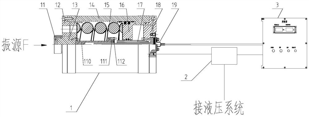
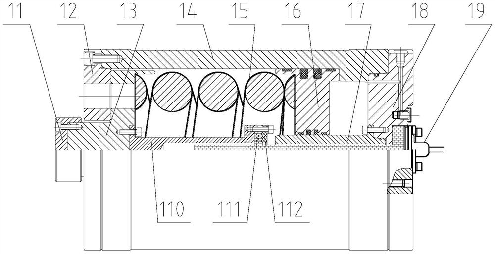
[0023] Such as figure 1 As shown, a vibration isolator based on hydraulic servo control provided by an embodiment of the present invention includes a vibration isolation element 1 , an integrated valve block 2 and a control box 3 . The vibration isolation element 1 is installed between the vibration source and the controlled object. The vibration isolation element 1 includes a cylinder body 14, a spring 15, a piston 16, a front end cover 12, a rear end cover 18, a thrust support block 11, a spring pressing cap 13, a magnetic Ring 111, magnetic ring fixing device, displacement sensor 19. The front end cover 12 and the rear end cover 18 are fixedly installed at both ends of the cylinder body 14 . The rear end of the spr...


PUM


Abstract

The invention relates to a vibration isolator based on hydraulic servo control. The vibration isolator comprises a vibration isolation element, an integrated valve block and a control box. The vibration isolation element comprises a hydraulic cylinder, a spring, a piston, a thrust supporting block, a spring pressing cap, a magnetic ring and a displacement sensor. The rear end of the spring pressing cap is located in the hydraulic cylinder, the front end extends out of the front end of the hydraulic cylinder and can move in the axial direction relative to the hydraulic cylinder, the thrust supporting block is fixedly installed at the front end of the spring pressing cap, and the magnetic ring is fixedly installed at the rear end of the spring pressing cap. The piston is installed in the hydraulic cylinder, the spring is installed between the spring pressing cap and the piston, a sealing cavity is formed between the piston and the rear end of the hydraulic cylinder, and the sealing cavity is connected with an oil outlet of the integrated valve block through an oil pipe. The displacement sensor is fixedly installed at the rear end of the hydraulic cylinder, and a signal line is connected with the control box. The integrated valve block is connected into a hydraulic system, and a signal line is connected with the control box. The self-adaptive vibration source constant force is controlled through hydraulic servo, it is ensured that the displacement of a vibration source does not exceed a limit value, and the vibration isolation function is achieved within the full-load range.

Description

technical field [0001] The invention belongs to the technical field of vibration reduction and noise reduction, and in particular relates to a vibration isolator based on hydraulic servo control. Background technique [0002] By adding an elastic element in series between the vibration source and the controlled object, the response of the controlled object to the excitation of the vibration source can be reduced. The metal spring vibration isolator has a long application time and a wide range of uses. It has low natural frequency, large bearing range, and mechanical It has the advantages of stable performance, mature design calculation method, simple and mature manufacturing process, etc. However, in the operating environment where the vibration source excitation constant force component has a large variation range and the vibration source displacement is limited, the compression range of the metal spring vibration isolator is limited. By setting a displacement protection st...

Claims


Application Information

Patent Timeline
IPC IPC(8): F16F13/00F16F9/32F16F9/46
CPCF16F13/002F16F9/3207F16F9/465F16F9/3292F16F2230/08
Inventor 张立浩李燎原王磊李全超刘伟
Owner CHINA SHIP DEV & DESIGN CENT
Learn More