
Printing equipment capable of stably controlling printing gap and reducing solder projection and collapse

A technology for stable control and printing equipment, applied in printing, printing machines, rotary printing machines, etc., can solve problems such as solder paste collapse and cutter pressure reduction

Inactive Publication Date: 2021-10-29
桂图加
View PDF0 Cites 0 Cited by
  • Summary
  • Abstract
  • Description
  • Claims
  • Application Information

AI Technical Summary

Problems solved by technology

[0003] In the existing technology, the printing equipment is affected by temperature and extrusion force, and the gap change of the printing plate directly affects the thickness of the printing solder paste, especially when the stencil tension is large and the pressure of the squeegee is not very high, the increase of the printing gap will increase There is a problem of sharpening in the thickness of the printing, and the change in the gap between the printing plate will reduce the pressure of the cutter. If the pressure of the cutter is not enough, the solder paste will collapse. Therefore, a printing equipment that can stably control the printing gap and reduce the sharpening and collapse has come into being. pregnancy

Method used


Image

  • Printing equipment capable of stably controlling printing gap and reducing solder projection and collapse
  • Printing equipment capable of stably controlling printing gap and reducing solder projection and collapse
  • Printing equipment capable of stably controlling printing gap and reducing solder projection and collapse

Examples


Embodiment Construction

[0020] The following will clearly and completely describe the technical solutions in the embodiments of the present invention with reference to the accompanying drawings in the embodiments of the present invention. Obviously, the described embodiments are only some, not all, embodiments of the present invention. Based on the embodiments of the present invention, all other embodiments obtained by persons of ordinary skill in the art without making creative efforts belong to the protection scope of the present invention.

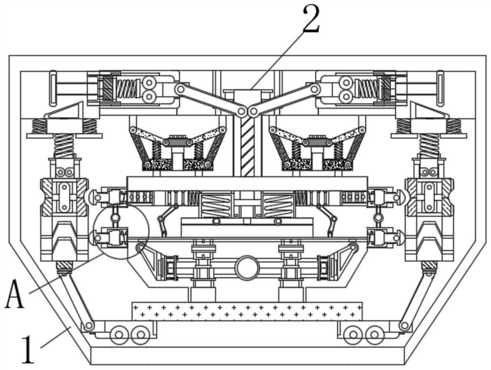
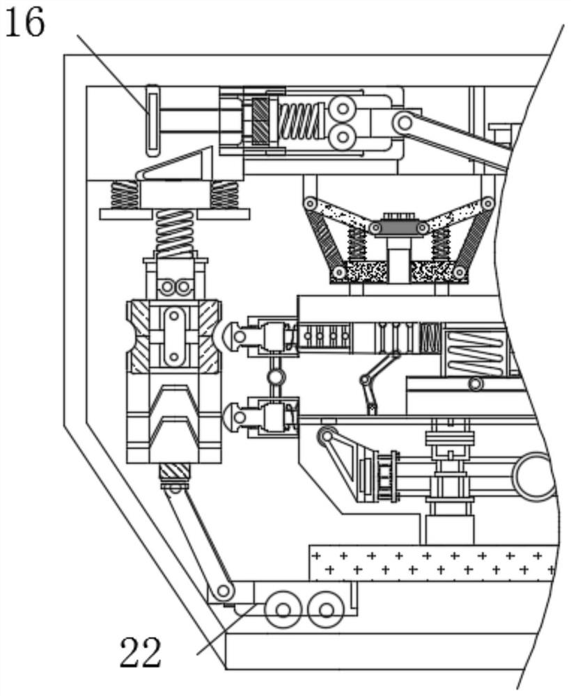
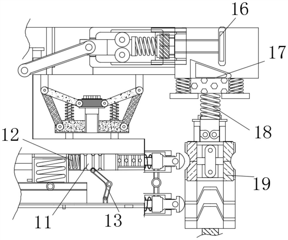
[0021] see Figure 1-5 , a printing device that stably controls the printing gap to reduce sharpening and collapse, including a body 1, the inside of the body 1 is movably connected with a push block 2, the surface of the push block 2 is movably connected with a driving mechanism, and the moving frame 4 is arranged at the bottom The parallel plate 5 is movably connected with a printed board 6, the bottom of the printed board 6 is movably connected with solder ...


PUM


Abstract

The invention relates to the technical field of printing, and provides printing equipment capable of stably controlling a printing gap and reducing solder projection and collapse. The printing equipment comprises a machine body, a push block is movably connected in the machine body, a push rod is fixedly connected to the bottom of the push block, and a moving frame is fixedly connected to the bottom of the push rod. According to the printing equipment capable of stably controlling the printing gap and reducing solder projection and collapse, a drive mechanism drives the push block to move, the push block and the push rod are used in cooperation to push the moving frame, the moving frame enables a printing plate to move for printing through parallel plates, when the printing plate inclines, the parallel plates incline to enable a balance lever to deviate, the balance lever extrudes pressure-sensitive ceramic through contact blocks, the pressure-sensitive ceramic is pressed to enable electromagnets to be powered on, the power-on amount is related to the magnitude of the pressure borne by the pressure-sensitive ceramic, the electromagnets attract iron blocks to move after being powered on, the iron blocks and turning rods jointly act to change the inclination angle of the printing plate, the printing plate is parallel to the horizontal plane again, the printing gap is kept stable, and thus solder projection is prevented.

Description

technical field [0001] The invention relates to the technical field of printing, in particular to a printing device which stably controls the printing gap and reduces sharpening and collapse. Background technique [0002] Printing is a technology that transfers the ink to the surface of the material through the plate-making, ink application, and pressurization processes of text, pictures, photos, anti-counterfeiting, etc., and reproduces the content of the original in batches. With the development of the times, printing technology is constantly updated. The technology is satisfied with mass production, the printing efficiency is fast, and the labor cost is reduced. The printing technology is applied to the advertising and media industries. [0003] In the existing technology, the printing equipment is affected by temperature and extrusion force, and the gap change of the printing plate directly affects the thickness of the printing solder paste, especially when the stencil t...

Claims


Application Information

Patent Timeline
Patent Type & Authority Applications(China)
IPC IPC(8): B41F17/00
CPCB41F17/00
Inventor 桂图加
Owner 桂图加
Learn More