A New Type of Automatic Separator
A splitter, automatic technology, applied in metal processing and other directions, can solve problems such as low production efficiency
- Summary
- Abstract
- Description
- Claims
- Application Information
AI Technical Summary
Problems solved by technology
Method used
Image
Examples
Embodiment 1
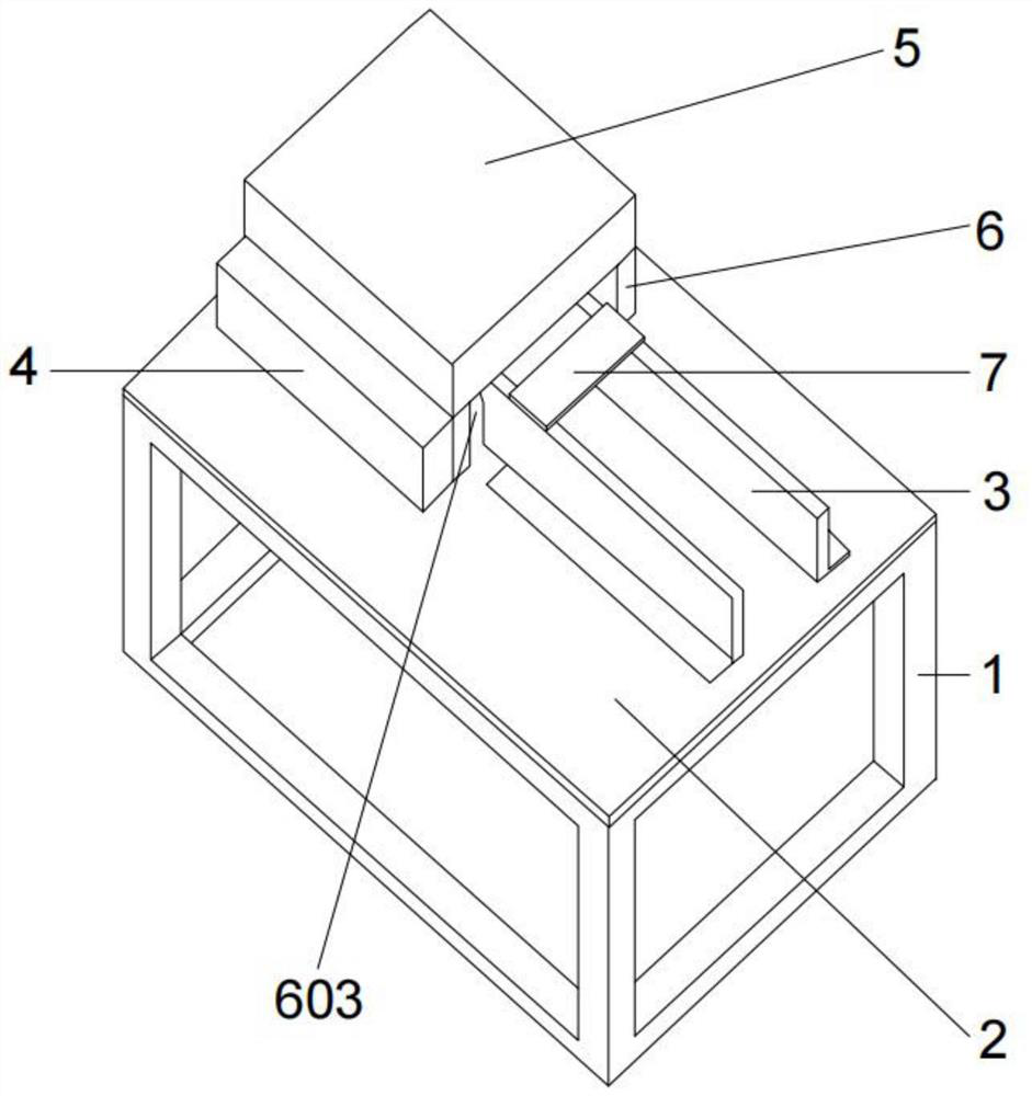
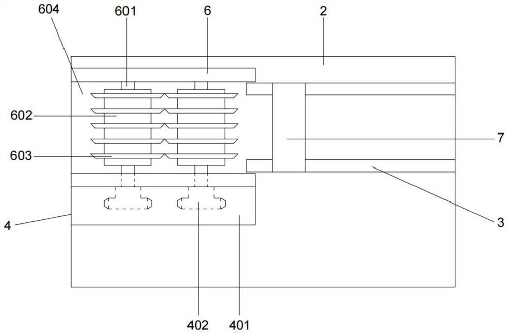
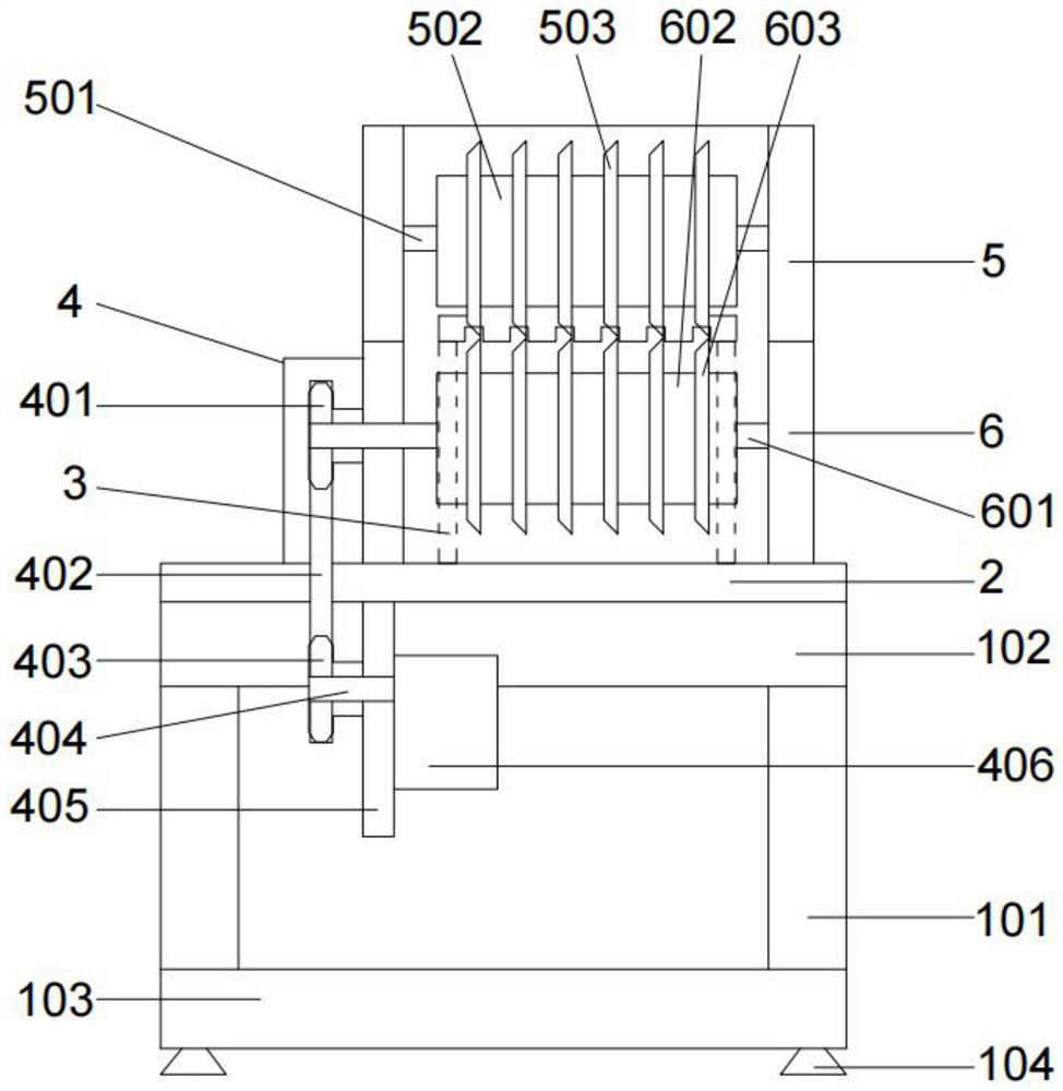
[0055] The embodiment of the present invention provides a new type of automatic plate dividing machine, such as Figure 1-Figure 3 As shown, it includes a frame body 1, a mounting plate 2, a positioning rail 3 and a cutting device, the upper end of the frame body 1 is fixedly connected with a mounting plate 2, and the upper end of the mounting plate 2 is provided with: the positioning rail 3 is connected to the upper The cutting device, the positioning track 3 is used to place the PCB board, the cutting device includes a power device, an active cutting device and a driven cutting device, the active cutting device includes an active cutting cover 6, and the inside of the active cutting cover 6 A number of driving blades 603 are rotatably provided, and the distance and number of the driving blades 603 are adjustable. The driven cutting device includes a driven cutting cover 5, and a number of driven blades 503 and a number of driven cutting cover 5 are rotated inside the driven c...
Embodiment 2
[0062] On the basis of the above Example 1, as Figure 4 As shown, the inner side of the positioning rail 3 is evenly spaced with a plurality of card slots 302, and the rails arranged on the front side of the positioning rail 3 are evenly spaced with a number of through holes 303, and the through holes 303 are provided with bearings 304 inside. , the positioning rail 3 and the positioning plate 7 are detachably connected by bolts 702, the positioning rail 3 is evenly spaced with positioning holes 301, the positioning plate 7 is evenly distributed with a number of movable holes 701, the positioning holes 301 It is fastened with the movable hole 701 through the bolt 702 .
[0063] The beneficial effects of the above technical solutions are:
[0064] By setting the positioning plate 7, the PCB board can be supported, and the position of the positioning plate 7 can be moved according to the length of the PCB board. , the purpose of detachable connection between the positioning p...
Embodiment 3
[0066] On the basis of Example 1, as image 3 As shown, the frame body 1 includes four uprights 101, the four uprights 101 are respectively arranged between the top corners of the top frame 102 and the bottom frame 103, and the top frame 102 and the bottom frame 103 are four profiles The rectangular frame is formed by connecting in sequence, the upper end of the top frame 102 is fixedly connected with the mounting plate 2 , and the top corners of the lower end of the bottom frame 103 are respectively provided with support pads 104 .
[0067] The beneficial effects of the above technical solutions are:
[0068] The upright column 101 is used to connect the top frame 102 and the bottom frame 103 fixedly. Setting the bottom frame 103 can enhance the stability of the frame body 1, and setting the support pad 104 can buffer the frame body 1 to prevent the automatic splitter from shaking. The offset of the PCBA of the connecting board causes the PCB board to be scrapped.
PUM
 Abstract
Description
Claims
Application Information
 - R&D
- Intellectual Property
- Life Sciences
- Materials
- Tech Scout
- Unparalleled Data Quality
- Higher Quality Content
- 60% Fewer Hallucinations
Browse by: Latest US Patents, China's latest patents, Technical Efficacy Thesaurus, Application Domain, Technology Topic, Popular Technical Reports.
© 2025 PatSnap. All rights reserved.Legal|Privacy policy|Modern Slavery Act Transparency Statement|Sitemap|About US| Contact US: help@patsnap.com


