Optical engine

An optical engine and light source technology, applied in the field of optical engines, can solve the problems of reducing the effect of lens transmission imaging, red light and green light do not meet the requirements, and affect the conversion efficiency of fluorescent layer 1, so as to ensure conversion performance and avoid transmission imaging The effect is poor, and the effect of ensuring the effect of transmission imaging

Pending Publication Date: 2021-10-26
QINGDAO HISENSE LASER DISPLAY CO LTD
View PDF0 Cites 0 Cited by
  • Summary
  • Abstract
  • Description
  • Claims
  • Application Information

AI Technical Summary

Problems solved by technology

In this way, the fluorescent layer is easy to accumulate a large amount of heat per unit time due to receiving high-energy blue light, causing the temperature of the fluorescent layer 1 to be too high, thereby affecting the conversion efficiency of the fluorescent layer 1 to blue light, thereby easily making red light and green light Does not meet the requirements, reducing the transmission imaging effect of the lens

Method used


Image

  • Optical engine
  • Optical engine
  • Optical engine

Examples


Embodiment Construction

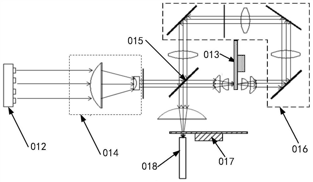
[0047] In order to make the purpose, technical solution and advantages of the present application clearer, a light source using a fluorescent wheel is introduced next.

[0048] Such as figure 2 As shown, the light source 01 includes a light-emitting device 012, a fluorescent wheel 013, a light-condensing assembly 014, a dichroic mirror 015, a mirror assembly 016, a color filter 017, and a homogenizer 018; wherein, the light-emitting device 012, the light-condensing assembly 014 , the dichroic mirror 015 and the fluorescent wheel 013 are sequentially arranged along the same straight line, the light exit port of the light emitting device 012 faces the light incident side of the light concentrating component 014, the light exit side of the light concentrating component 014 faces the transmission surface of the dichroic mirror 015, and The plane where the dichroic mirror 015 is located forms an included angle with the center line of the incident beam, the light incident side of t...


PUM


Abstract

The invention discloses an optical engine, and belongs to the technical field of projection. The optical engine comprises a light source, an optical-mechanical system and a lens. The light source comprises a light source shell, a light-emitting device and a fluorescent wheel. The fluorescent wheel comprises a fluorescent piece, a heat dissipation plate, a substrate and a driving part. The light-emitting device and the driving part are fixed in the light source shell, the substrate is fixedly connected with a rotating shaft of the driving part, the heat dissipation plate and the fluorescent sheet are sequentially fixed on the substrate, and a light outlet of the light-emitting device faces the fluorescent sheet; the light inlet side of the optical-mechanical system faces the light outlet side of the light source shell; the lens is fixed on the light outlet side of the optical-mechanical system. In the embodiment of the invention, the heat gathered on the fluorescent sheet can be transferred to the heat dissipation plate for heat dissipation, and meanwhile, part of the heat transferred to the heat dissipation plate can be continuously transferred to the substrate for heat dissipation, so that the heat dissipation efficiency of the heat on the fluorescent sheet is improved, the problem of poor transmission imaging effect of the lens is avoided, and the transmission imaging effect of the optical engine is ensured.

Description

technical field [0001] The present application relates to the field of projection technology, in particular to an optical engine. Background technique [0002] With the continuous development of science and technology, optical engines are more and more used in people's work and life, mainly for emitting light beams to transmit images on projection screens. [0003] In related technologies, the optical engine mainly includes a light source, an optical-mechanical system, and a lens. The light source includes a light source housing, a light-emitting device, and a fluorescent wheel. The light-emitting device and the fluorescent wheel are fixed in the light source housing, and the fluorescent wheel is located on the light outlet side of the light-emitting device. , the fluorescent wheel is used to convert the blue light emitted by the light-emitting device into red light and green light, and reflect it to the optomechanical system; The blue light and the red light and green ligh...

Claims


Application Information

Patent Timeline
Patent Type & Authority Applications(China)
IPC IPC(8): G03B21/20G03B21/16G02B26/00
CPCG03B21/204G03B21/16G02B26/008
Inventor 逄相来张勇
Owner QINGDAO HISENSE LASER DISPLAY CO LTD
Why Eureka
Try Eureka