
Nuclear power plant buried hydrogen pipeline leakage monitoring system and method

A technology for monitoring systems and nuclear power plants, applied in pipeline systems, gas/liquid distribution and storage, mechanical equipment, etc., can solve problems such as hydrogen leakage, hydrogen monitoring devices alarming for no reason, unable to locate, etc., and achieve the effect of improving reliability

Active Publication Date: 2021-10-26
SANMEN NUCLEAR POWER CO LTD
View PDF10 Cites 1 Cited by
  • Summary
  • Abstract
  • Description
  • Claims
  • Application Information

AI Technical Summary

Problems solved by technology

[0004] The first type of airtight casing can only detect hydrogen leakage, but cannot locate it. At the same time, once the airtight fiberglass casing is cracked in the ground, the monitoring ability will be completely lost.
[0005] Although the second type can realize monitoring and preliminary positioning, since both ends of the casing must be opened for pumping, in practical applications, due to water entering the casing (or casing cracking in rainy days), the pumping will be accompanied by water vapor and cause the hydrogen monitoring device to fail. Frequent and unreasonable alarm
At the same time, this solution requires more pipelines and equipment, which is not conducive to investment and equipment operation and maintenance.

Method used


Image

  • Nuclear power plant buried hydrogen pipeline leakage monitoring system and method
  • Nuclear power plant buried hydrogen pipeline leakage monitoring system and method
  • Nuclear power plant buried hydrogen pipeline leakage monitoring system and method

Examples


Embodiment

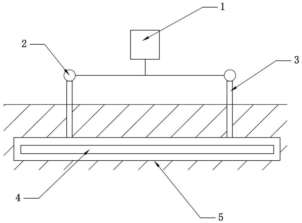
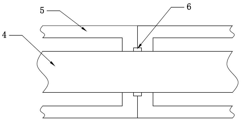
[0032] In this embodiment, a nuclear power plant buried hydrogen pipeline leakage monitoring system, such as figure 1 , figure 2 As shown, it includes a sleeve 5, a hydrogen concentration probe 2 and a control unit 1. The hydrogen pipeline 4 is arranged in the sleeve 5. The end surface of the sleeve 5 is provided with a through hole and a sealing groove. The diameter of the through hole is the same as that of the hydrogen pipeline. The groove is arranged around the through hole, and a sealing ring 6 is arranged in the sealing groove, and two adjacent casings share a sealing ring 6. Under the action of the sealing ring, the casing and the hydrogen pipeline form a closed space, so that there is no hydrogen leakage When there is no air flow inside the casing. The casing 5 is provided with a vertical pipe 3, the vertical pipe 3 is arranged at both ends of the casing, the hydrogen concentration probe 2 is arranged at the upper end of the vertical pipe 3, the hydrogen concentratio...


PUM


Abstract

The invention relates to a nuclear power plant buried hydrogen pipeline leakage monitoring system and method. The system comprises a sleeve, hydrogen concentration probes and a control unit. A hydrogen pipeline is arranged in the sleeve, the sleeve and the hydrogen pipeline form a closed space, vertical pipes are arranged on the sleeve and arranged at the two ends of the sleeve, and the hydrogen concentration probes are arranged at the upper ends of the vertical pipes and connected with the control unit. The method comprises the steps of acquiring the time difference of trigger alarms of the two hydrogen concentration probes; acquiring the gas flow rates detected by two gas flow rate sensors; preliminary positioning a leakage point, and determining a leakage section; and positioning the leakage point. The nuclear power plant buried hydrogen pipeline leakage monitoring system and method have the advantages that the leakage point can be accurately positioned, the requirement for the leakproofness of the glass fiber reinforced plastic sleeve is not high, and even though the glass fiber reinforced plastic sleeve is broken, monitoring of hydrogen pipeline leakage is not affected; and no fear that water enters the glass fiber reinforced plastic sleeve exists, a series of facilities such as a hydrogen sampling pipeline and a sampling pump are reduced, faults of an analysis instrument are dispersed to all measuring point instruments, and the reliability is improved.

Description

technical field [0001] The invention relates to the field of gas leakage detection, in particular to a system and method for monitoring the leakage of buried hydrogen pipelines in nuclear power plants. Background technique [0002] Part of the process of the nuclear power plant requires the participation of high-pressure hydrogen, so a hydrogen supply station sub-item is built as a supporting component. The hydrogen supply pipeline is directly buried underground before entering the steam turbine of the nuclear power plant or the nuclear island building. Considering that hydrogen is a flammable and explosive gas, it is necessary to monitor the leakage of buried hydrogen pipelines. [0003] There are two main monitoring methods currently used in nuclear power. One is to cover the buried hydrogen pipeline with a closed FRP casing, and fill the closed casing with nitrogen, and monitor the leakage of the hydrogen pipeline through a pressure gauge. Once the hydrogen pipeline leak...

Claims


Application Information

Patent Timeline
Patent Type & Authority Applications(China)
IPC IPC(8): F17D5/06
CPCF17D5/06Y02E30/30
Inventor 吕永焕李拓楼开宏黄玉轩郭嗣登陶慧杰李亮罗艾青张力文
Owner SANMEN NUCLEAR POWER CO LTD
Learn More