


Quick Research
Generate reliable direction feasibility study reports for your R&D in just a few steps.

Technical Q&A
Discover and master advanced knowledge NOW. Basics, ideas, possibilities, all at once.

Find Solutions
As an expert in R&D theories, this can generate solutions to your technical problems instantly.

Evaluate Feasibility
Analyze your overall solution with one click, know your potential R&D risks in advance.

Monitor Landscape
Get weekly tech updates, stay abreast of the latest tech innovations and key insights.
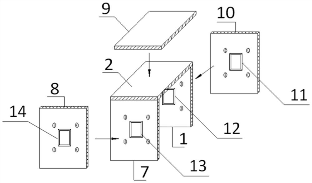
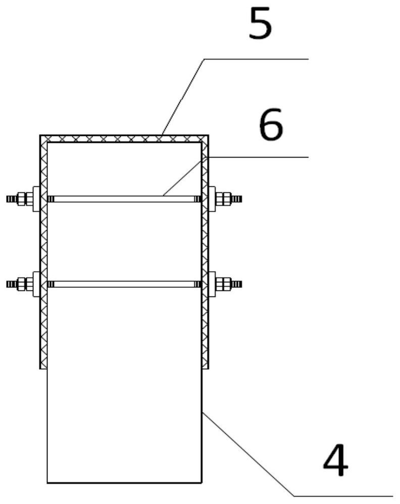
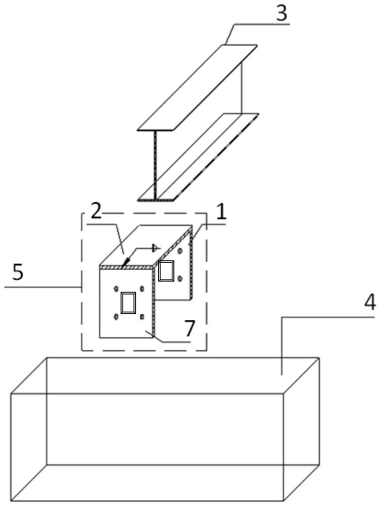
Rear connecting device and method for solid-web steel beam and concrete beam
A technology for reinforced concrete beams and connecting devices, applied in joists, girders, truss beams, etc., can solve the problems of steel bar collision, failure to meet steel beam connection requirements, and high engineering costs
- Summary
- Abstract
- Description
- Claims
- Application Information
AI Technical Summary
Problems solved by technology
Method used
Image

Examples
Embodiment Construction
[0027] Embodiments of the present invention provide a rear connection device and method for solid-web steel beams and concrete beams, which will be described below with reference to the accompanying drawings.
[0028] In the existing project, since the steel plate is not pre-embedded in the concrete beam, the connection requirements of the steel beam cannot be met. When the solid web steel beam is placed on the upper part of the concrete beam and the connection node is located at the end of the beam, the steel bars at the upper part of the beam end are generally densely arranged, and the rear anchor bolts are likely to collide with the steel bars in the concrete beam, resulting in the rear anchor bolts failing to meet the design requirements , when the force is transmitted, the anchor bolt should be loose, and the joint should be damaged, causing the anchor plate to fall off. Secondly, the rear anchor bolt at the upper part of the beam end is likely to affect the steel bars in...
PUM
 Abstract
Description
Claims
Application Information
 - R&D Engineer
- R&D Manager
- IP Professional
- Industry Leading Data Capabilities
- Powerful AI technology
- Patent DNA Extraction
Browse by: Latest US Patents, China's latest patents, Technical Efficacy Thesaurus, Application Domain, Technology Topic, Popular Technical Reports.
© 2024 PatSnap. All rights reserved.Legal|Privacy policy|Modern Slavery Act Transparency Statement|Sitemap|About US| Contact US: help@patsnap.com