Anchoring device for heart implant prosthesis and heart implant prosthesis comprising same

An anchoring device and implant technology, applied in the field of medical devices, can solve problems such as insufficient fit of heart tissue, displacement of valve prosthesis, and insufficient anchoring force, so as to facilitate adhesion and proliferation, reduce frictional damage, The effect of firm anchoring

Pending Publication Date: 2021-06-25
SHANGHAI TRULIVE MEDTECH CO LTD
View PDF2 Cites 0 Cited by
  • Summary
  • Abstract
  • Description
  • Claims
  • Application Information

AI Technical Summary

Problems solved by technology

If the anchoring member is too rigid and placed at the apex of the heart, it may not fit well with the heart tissue, resulting in bleeding, or rubbing against the heart tissue to cause bleeding, etc.
If the stiffness of the anchor is too small, it may cause insufficient anchoring force and displacement of the valve prosthesis

Method used


Image

  • Anchoring device for heart implant prosthesis and heart implant prosthesis comprising same
  • Anchoring device for heart implant prosthesis and heart implant prosthesis comprising same
  • Anchoring device for heart implant prosthesis and heart implant prosthesis comprising same

Examples


Embodiment 1

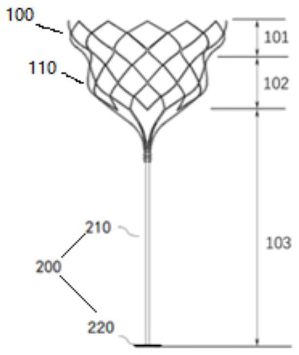
[0042] This embodiment provides a mitral valve prosthesis. The mitral valve prosthesis includes a valve part 100 and an anchoring device 200. The valve part 100 includes a valve support 110, a skirt and an artificial valve leaflet. Such as figure 1 As shown, the valve stent 110 can be divided into a first area 101 , a second area 102 and a third area 103 longitudinally. After the mitral valve prosthesis 100 is implanted in the human body, the first area 101 is attached to the original mitral valve annulus of the heart to prevent the valve prosthesis from falling from the left atrium into the left ventricle, and the second area 102 is used to carry the artificial valve leaflets 130, at the same time relying on the support on the tissue to play a certain role of fixation and sealing; the third area 103 is the anchoring part of the mitral valve prosthesis in the left ventricle, preventing the prosthesis from being impacted by blood to the left atrium when it is closed .

[0043...

Embodiment 2

[0069] This embodiment provides an anchoring device for a chordal prosthesis, such as Figure 4 As shown, the anchoring device includes an anchoring body, the anchoring body is fixed at the end of the chordal prosthesis 100; the surface of the anchoring body is covered with a polymer coating with liquid absorption capacity, wherein the polymer coating The layer has a swollen morphology after imbibition.

[0070] The chordal prosthesis is used to replace the damaged chordae. One end of the chordal prosthesis is fixed to the valve leaflet, and the other end is anchored through the anchoring body. For example, the anchoring body can be attached to the apical epicardium or papillary muscle.

[0071] The anchoring body in this embodiment can adopt a structure similar to that of any embodiment in Embodiment 1, so as to realize the anchoring of the chordal prosthesis 100 .

[0072] It should be noted that, on the one hand, the polymer coating in the above examples can absorb liquid ...


PUM


Abstract

The invention discloses an anchoring device for a heart implant prosthesis, which comprises an anchoring main body, and the anchoring main body is fixed at the end part of an implant; and the surface of the anchoring main body is covered with a polymer coating with liquid absorbing capacity, and the polymer coating has an expanded form after absorbing liquid. A heart implant prosthesis is also disclosed. The implant prosthesis can be a valve prosthesis or a chordae tendineae prosthesis, the implant prosthesis is attached to tissues such as the apex adventitia, the ventricular wall and the papillary muscle through the anchoring main body to provide anchoring force, and when seepage occurs on the surface, making contact with the tissues, of the anchoring main body, the polymer coating arranged on the surface of the anchoring main body can absorb the seepage and expand, and the polymer coating becomes flexibile; the volume of the polymer coating which absorbs liquid and expands is increased, so that sealing can be assisted, and further leakage is prevented; and in addition, the hydrophilicity of the polymer coating contributes to adhesion and proliferation of endothelial cells, thereby contributing to endothelialization of the anchoring body.

Description

technical field [0001] The invention relates to the technical field of medical devices, in particular to an anchoring device for heart implant prosthesis anchoring and a heart implant prosthesis comprising the same. Background technique [0002] The heart contains four chambers, the right atrium (RA), right ventricle (RV), left atrium (LA) and left ventricle (LV). The pumping action of the left and right sides of the heart generally occurs simultaneously throughout the cardiac cycle. The valve that separates the atria from the ventricles is called the atrioventricular valve. The atrioventricular valve acts as a one-way valve to ensure the normal flow of blood in the heart chambers. The atrioventricular valve between the left atrium and left ventricle is the mitral valve, and the atrioventricular valve between the right atrium and right ventricle is the tricuspid valve. The pulmonary valve directs blood flow to the pulmonary artery and from there to the lungs, where blood r...

Claims


Application Information

Patent Timeline
Patent Type & Authority Applications(China)
IPC IPC(8): A61F2/24
CPCA61F2/24A61F2/2418A61F2/2457A61F2220/0016
Inventor 赵婧闻靖
Owner SHANGHAI TRULIVE MEDTECH CO LTD
Why Eureka
Try Eureka