Eureka AIR delivers breakthrough ideas for toughest innovation challenges, trusted by R&D personnel around the world.

Air conditioner air supply system and method for rail transit vehicle

A technology for rail transit vehicles and air supply systems, applied in the field of air-conditioning air supply systems, can solve the problems of high noise, single return air position, uneven return air, etc., and achieve the effects of reducing power consumption and reducing return air noise

Inactive Publication Date: 2021-10-26
CHONGQING CRRC RAILWAY VEHICLES CO LTD
View PDF9 Cites 1 Cited by
  • Summary
  • Abstract
  • Description
  • Claims
  • Application Information

AI Technical Summary

Problems solved by technology

[0003] The invention provides an air-conditioning air supply system and method for rail transit vehicles, which can improve the problems of single return air position, uneven return air, and high noise of rail transit vehicles, without adding too many return air devices

Method used


Image

  • Air conditioner air supply system and method for rail transit vehicle
  • Air conditioner air supply system and method for rail transit vehicle

Examples


Embodiment 1

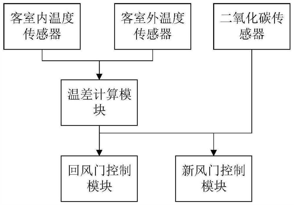
[0037] Embodiment 1 is basically as attached figure 1 Shown:

[0038] An air-conditioning air supply system for a rail transit vehicle, comprising a passenger interior temperature sensor, a passenger exterior temperature sensor, a return air door control module, and a fresh air door control module. The temperature sensor inside the passenger room is used to detect the temperature inside the passenger room; the temperature sensor outside the passenger room is used to detect the temperature outside the passenger room. The temperature sensor in the passenger room is set on the air return door and the air return port, and the air return port is located in the gap of the air duct. The return air position of the air conditioner in the existing rail transit vehicles is single, and the return air speed is relatively fast, resulting in large return air noise. In the present invention, the return air is carried out by utilizing the space of the air duct in the passenger room, and the ...

Embodiment 2

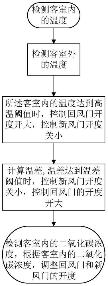
[0045] Embodiment 2 is basically as attached figure 2 Shown:

[0046] An air-conditioning air supply method for a rail transit vehicle, comprising the following steps:

[0047] S1: Detect the temperature in the passenger room through the temperature sensor in the passenger room; the temperature sensor in the passenger room is set at the air return door and the air return port; the air return port is located in the gap of the air duct;

[0048] S2: Detect the temperature outside the passenger room through the temperature sensor outside the passenger room;

[0049] S3: Control the opening of the return air door and the fresh air door; when the temperature in the passenger compartment reaches a high temperature threshold, control the opening of the return air door to be large, and control the opening of the fresh air door to be small.

[0050] The opening degrees of the return air door and the fresh air door include full opening, 2 / 3 opening, 1 / 3 opening and full closing. Aft...


PUM


Abstract

The invention relates to the technical field of rail transit and particularly relates to an air conditioner air supply system and method for a rail transit vehicle. The system comprises guest room temperature sensors, guest room temperature sensors, a return air door control module and a fresh air door control module, wherein the return air door control module is used for controlling an opening degree of a return air door; when the temperature in the guest room reaches a high-temperature threshold value, the opening degree of the return air door is controlled to be large; the fresh air door control module is used for controlling an opening degree of a fresh air door; when the temperature in the guest room reaches a high-temperature threshold value, the opening degree of the fresh air door is controlled to be small; the guest room temperature sensors are arranged on the return air door and a return air inlet; and the return air inlet is formed in an air duct gap. The system is advantaged in that problems that a rail transit vehicle is single in air return position, uneven in air return and large in noise can be solved, and excessive air return devices do not need to be additionally arranged.

Description

technical field [0001] The invention relates to the technical field of rail transit, in particular to an air-conditioning air supply system and method for rail transit vehicles. Background technique [0002] The return air in the air conditioner refers to the circulation of indoor air, while the fresh air refers to the suction of new outdoor air. For rail transit vehicles, the return air of the air conditioner is set in the passenger compartment, that is, in the compartment where the passengers in the rail transit vehicle are located, and the fresh air door is set outside the compartment. The development of the city promotes the improvement of the hardware facilities in the city, and the continuous construction of the subway has become an indispensable means of transportation for people's daily travel. However, the air-conditioning system of the rail transit vehicles still needs to be improved. In the existing rail transit vehicles, the return air point is generally set in ...

Claims


Application Information

Patent Timeline
IPC IPC(8): B61D27/00
CPCB61D27/0018
Inventor 于文晶杨芬王麒皓水新虎赵玉宝姚鸿洲廖承州谢川江金生陈亮
Owner CHONGQING CRRC RAILWAY VEHICLES CO LTD
Why Eureka
Eureka Blog
Learn More