Sine wave rotor based on permanent magnet and outer rotor iron core eccentric structure design

An eccentric structure and external rotor technology, applied in the direction of magnetic circuit shape/style/structure, magnetic circuit rotating parts, magnetic circuit, etc., can solve the problem of affecting the performance and efficiency of the energy storage flywheel generator and the large harmonic content of the back electromotive force waveform , affect the performance and efficiency of the motor, and achieve the effect of improving the waveform of the back electromotive force, reasonable changes in the radial thickness of the air gap, and saving permanent magnet materials

Active Publication Date: 2021-10-22
安徽华驰动能科技有限公司
View PDF8 Cites 0 Cited by
  • Summary
  • Abstract
  • Description
  • Claims
  • Application Information

AI Technical Summary

Problems solved by technology

[0002] Traditional permanent magnet synchronous motors are mostly used in high-speed applications and require high speed regulation accuracy. Therefore, they are mostly driven and controlled by sine wave phase current. The sine wave phase current needs to interact with the opposite electromotive force of the sine wave to reduce the electromagnetic rotation speed. Torque pulsation, while the traditional maglev energy storage flywheel permanent magnet motor has a large content of 3rd, 5th, and 7th harmonics in the back electromotive force waveform, which causes the motor to generate electromagnetic torque pulsation, affecting the performance and efficiency of the motor
The main reason for the large harmonic content of the back electromotive force waveform of the magnetic levitation energy storage flywheel permanent magnet motor is that the sinusoidal waveform of the air gap magnetic field of the motor is poor, and more odd harmonics are mixed in, making the air gap magnetic field of the motor close to trapezoidal, so The harmonic content of the back EMF waveform is large
[0003] Similarly, the traditional sine wave energy storage flywheel generator is also driven and controlled by the sine wave phase current. The sine wave phase current needs to interact with the sine wave opposite electromotive force to reduce the electromagnetic torque ripple, while the traditional coreless permanent magnet The 4th, 6th, and 7th harmonic content in the energy storage flywheel generator is relatively large in the back electromotive force waveform, which causes the energy storage flywheel generator to generate electromagnetic torque pulsations, which affects the performance and efficiency of the energy storage flywheel generator. The main reason for the large harmonic content of the back electromotive force waveform of the magnetic energy storage flywheel generator is that the sinusoidal waveform of the air gap magnetic field of the energy storage flywheel generator is poor, and more odd harmonics are mixed in, so that the energy storage flywheel generator The air gap magnetic field is close to trapezoidal, so the harmonic content of the back EMF waveform is large

Method used


Image

  • Sine wave rotor based on permanent magnet and outer rotor iron core eccentric structure design
  • Sine wave rotor based on permanent magnet and outer rotor iron core eccentric structure design
  • Sine wave rotor based on permanent magnet and outer rotor iron core eccentric structure design

Examples


Embodiment 1

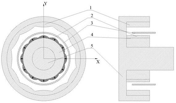
[0033] Embodiment 1 discloses a sine wave rotor designed based on a permanent magnet and an eccentric structure of an outer rotor iron core used in a permanent magnet synchronous motor with a magnetic levitation energy storage flywheel. Reference attached figure 1 And attached figure 2, which includes an outer rotor core 1, an eccentric permanent magnet 2, a magnetic levitation energy storage flywheel stator 3, an inner rotor core 4 and a rotor shaft 5, and the outer rotor core 1 and the inner rotor core 4 are fixedly connected to the rotor shaft 5, so that The outer rotor core 1 and the inner rotor core 4 rotate together with the rotor shaft 5 . In the specific setting process, the radially outer side of the outer rotor core 1 is installed on the outer end of the rotor shaft 5, and the radially inner side of the inner rotor core 4 is installed on the inner end of the rotor shaft. Several eccentric permanent magnets 2 are placed alternately along the radially outer side of ...

Embodiment 2

[0050] Embodiment 2 discloses a sine wave rotor designed based on a permanent magnet and an eccentric structure of an outer rotor iron core used in a hollow cup sine wave energy storage flywheel generator. Reference attached Figure 4 , attached Figure 5 And attached Figure 6 , which includes an outer rotor core 1 , an eccentric permanent magnet 2 , a tile-shaped magnetic isolation block 6 , a hollow cup stator 3 , an inner rotor core 4 and a rotor shaft 5 . Both the outer rotor core 1 and the inner rotor core 4 are fixedly connected to the rotor shaft 5 , so that the outer rotor core 1 and the inner rotor core 4 can rotate together with the rotor shaft 5 . In the specific setting process, the radially outer side of the outer rotor core 1 is installed on the outer end of the rotor shaft 5 , and the radially inner side of the inner rotor core 4 is installed on the inner end of the rotor shaft 5 . Several eccentric permanent magnets 2 are placed alternately along the radial...


PUM

PropertyMeasurementUnit
thicknessaaaaaaaaaa
thicknessaaaaaaaaaa

Abstract

The invention relates to the technical field of motors, and particularly discloses a sine wave rotor based on a permanent magnet and outer rotor iron core eccentric structure design. The sine wave rotor comprises an outer rotor iron core, eccentric permanent magnets, a stator, an inner rotor iron core and a rotor shaft, the multiple eccentric permanent magnets are alternately placed on the inner rotor iron core, each eccentric permanent magnet is composed of an arc edge inner contour, an eccentric arc outer contour and two side edges, the outer contour of the outer rotor iron core is circular, the inner contour is composed of a plurality of eccentric arcs protruding inwards in the circumferential direction, the number of the eccentric arcs is the same as that of the eccentric permanent magnets, the positions of the eccentric arcs are in one-to-one correspondence with those of the eccentric permanent magnets, and annular air gaps are formed between the radial inner side of the outer rotor iron core and the eccentric permanent magnets. According to the invention, the rotor is designed based on the eccentric structure of the permanent magnet and the outer rotor core, the air-gap flux density waveform of the motor or the generator is improved, the harmonic content in an air-gap magnetic field is reduced, the air-gap magnetic field is close to sine waves, and the performance of the motor or the generator is improved.

Description

technical field [0001] The invention relates to the technical field of motors or generators, and specifically discloses a sine wave rotor designed based on permanent magnets and an eccentric structure of an outer rotor iron core. Background technique [0002] Traditional permanent magnet synchronous motors are mostly used in high-speed applications and require high speed regulation accuracy. Therefore, they are mostly driven and controlled by sine wave phase current. The sine wave phase current needs to interact with the opposite electromotive force of the sine wave to reduce the electromagnetic rotation speed. Torque pulsation, while the traditional maglev energy storage flywheel permanent magnet motor has a large content of 3rd, 5th, and 7th harmonics in the back electromotive force waveform, which causes the motor to generate electromagnetic torque pulsation and affects the performance and efficiency of the motor. The main reason for the large harmonic content of the back...

Claims


Application Information

Patent Timeline
Patent Type & Authority Applications(China)
IPC IPC(8): H02K1/27H02K16/02H02K21/02
CPCH02K1/2786H02K1/2753H02K16/02H02K21/028H02K2201/03H02K2201/06H02K2213/03Y02T10/64
Inventor 陈胜林苏森韩坤王志强
Owner 安徽华驰动能科技有限公司
Why Eureka
Try Eureka