Flat pressing device for mounting bottom cover of watch shell
A shell, flat pressing technology, applied in the direction of clocks, clocks, clock support equipment, etc., can solve the problems of reduced sealing performance and position deviation of the sealing ring, and achieve the effect of uniform extrusion, easy operation and improved sealing.
- Summary
- Abstract
- Description
- Claims
- Application Information
AI Technical Summary
Problems solved by technology
Method used
Image
Examples
Embodiment 1
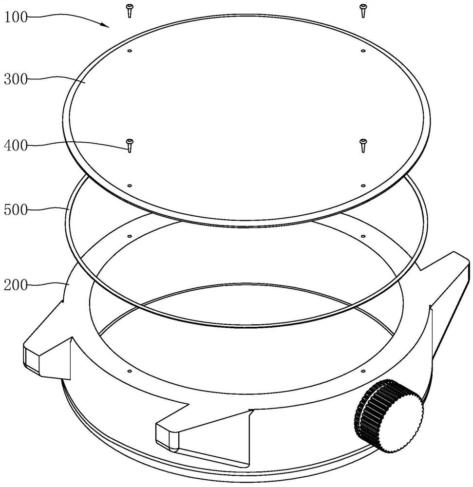
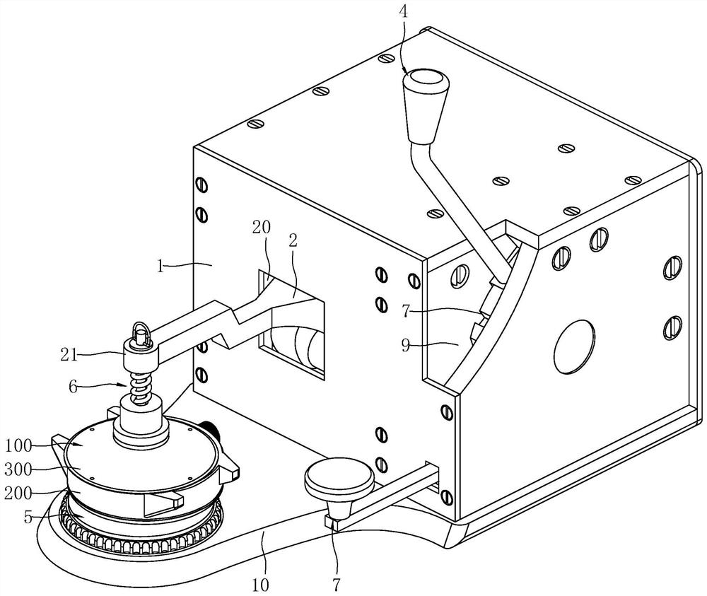
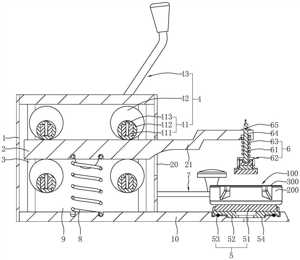
[0056] Refer figure 2 , 3 , Platen means for mounting the bottom cover of the watch case 1 comprises a base, a platen 2, a drive mechanism 4, the support means 5, platen means 6 and a locking mechanism 7; wherein 1 is provided with a solid base was vertically disposed the guide structure 3, a platen 2 disposed on the sliding guide structure 3, the platen 2 can be slid along the guide structure 3 up / down; the front side of the pressure plate 2 is integrally formed with outwardly extending arm 21 press, platen press mechanism 6 is provided on the arm 21 an end remote from the platen 2, so that the flat platen press mechanism 6 can be 2 with ascending / descending; 5 means 100 for carrying the support means 5 is provided is placed at the bottom of the wristwatch case base 1, the support means 5 and the pressure plate 2 to each other in the vertical direction staggered, and the support means 5 is located below the platen mechanism 6, so that the flat press mechanism 6 ascending / de...
Embodiment 2
[0079] Difference between the present embodiment is different from Example 1 in that the structure of the drive assembly 43.
[0080] Refer Figure 7 , Specifically, in the present embodiment, the drive assembly 43 includes a drive sprocket 435, two driven sprocket 436, a chain 437 and a drive member 433; wherein the second mounting chamber 12 features a base 1 along the widthwise direction extending spindle 434, both ends of the spindle 434 are rotatably disposed on opposite sides of the second mounting chamber 12 is provided, and the spindle 434 extending into the third receiving chamber 13; in the second drive sprocket 435 is mounted within the cavity 12 and the drive sprocket 435 fixed to the outer periphery of the spindle 434, drive sprocket 435 can be rotated with the main shaft 434; two driven sprocket 436 are located in the second mounting chamber 12, each driven sprocket 436 includes two shape configuration identical driven sprocket 436, sprocket 436 and the driven shaft 4...
Embodiment 3
[0083] This embodiment differs from the other embodiments in that the present embodiment is different from the structure of the drive mechanism 4.
[0084] Refer Figure 8 , Specifically, in the present embodiment, the drive mechanism 4 comprises a screw 44, nut driver 46 and housing 45; wherein the screw 44 is vertically disposed, and the bottom screw 44 is rotatably disposed on the base plate, the screw 44 top rotatably disposed through the top plate; the seat nut 45 connected to the screw threads 44 and nut holder 45 fixedly connected with the platen 2; 46 of the drive wheel, and the driver 46 is fixed to the top of the screw 44. When the wheel is rotated manually, the wheel can be driven by the lead screw 44 is rotated, and the screw 44 through the threaded connection between the drive nut seat 45 to drive the platen 2 along the sliding guide structure 3 up / down. In other embodiments, the driver 46 may take the form of manually breaking lever or the like, can also be in the f...
PUM
 Abstract
Description
Claims
Application Information
 - R&D Engineer
- R&D Manager
- IP Professional
- Industry Leading Data Capabilities
- Powerful AI technology
- Patent DNA Extraction
Browse by: Latest US Patents, China's latest patents, Technical Efficacy Thesaurus, Application Domain, Technology Topic, Popular Technical Reports.
© 2024 PatSnap. All rights reserved.Legal|Privacy policy|Modern Slavery Act Transparency Statement|Sitemap|About US| Contact US: help@patsnap.com


