
Filter element assembly and engine filter using same

A component and filter element technology, which is applied to engine components, machines/engines, fuel air filters, etc., can solve the problems of unable to clean filter element dust, and achieve the effects of ensuring service life, avoiding clogging, and convenient use

Active Publication Date: 2021-10-22
江苏富滤盛滤清器有限公司
View PDF7 Cites 2 Cited by
  • Summary
  • Abstract
  • Description
  • Claims
  • Application Information

AI Technical Summary

Problems solved by technology

[0004] The purpose of the embodiments of the present invention is to provide a filter element assembly, aiming to solve the problem that the existing filter element assembly cannot automatically clean the dust accumulated on the filter element

Method used


Image

  • Filter element assembly and engine filter using same
  • Filter element assembly and engine filter using same
  • Filter element assembly and engine filter using same

Examples


Embodiment Construction

[0032] In order to make the object, technical solution and advantages of the present invention clearer, the present invention will be further described in detail below in conjunction with the accompanying drawings and embodiments. It should be understood that the specific embodiments described here are only used to explain the present invention, not to limit the present invention.

[0033] The specific implementation of the present invention will be described in detail below in conjunction with specific embodiments.

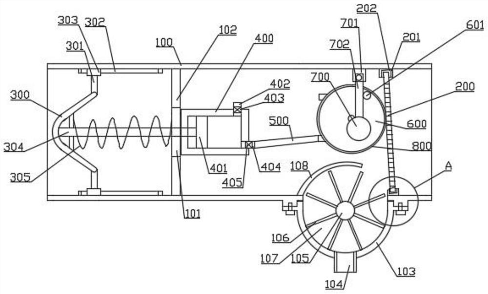
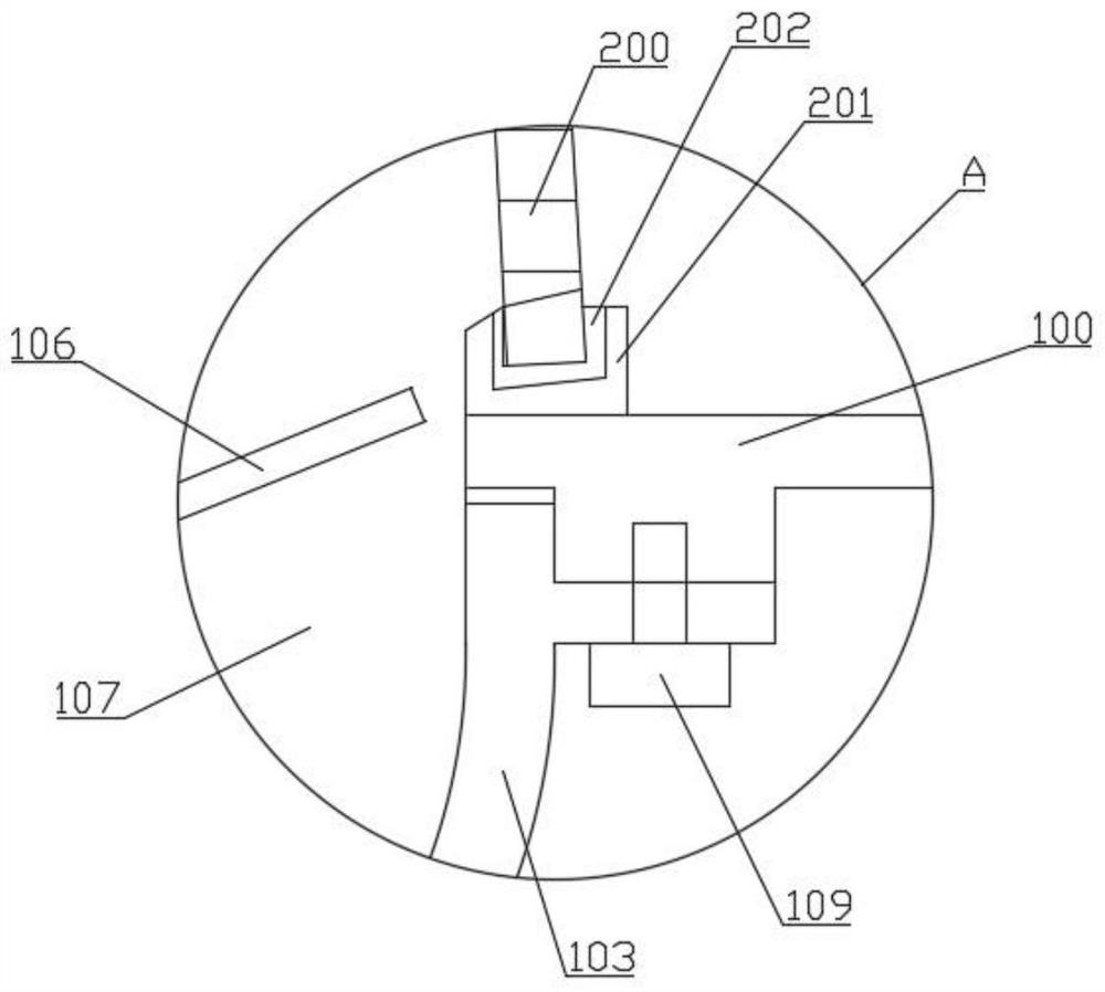
[0034] Such as figure 1 As shown, a structural diagram of a filter element assembly provided by an embodiment of the present invention, in an embodiment of the present invention, a filter element assembly, the filter element assembly includes:

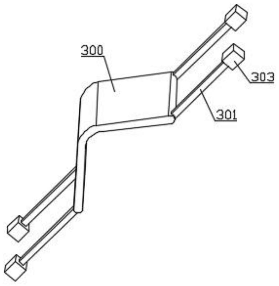
[0035] A buffer plate 300, the buffer plate 300 is arranged in the inner cavity of one side of the first housing 100 through an elastic member;

[0036] A filter screen 200, the filter screen 200 is obliquely arranged i...


PUM


Abstract

The invention is suitable for the technical field of engine filters, and provides a filter element assembly which comprises a buffer plate, a filter screen, an air supply assembly and an impact piece, and the buffer plate is arranged in an inner cavity in one side of a first shell through an elastic piece; the filter screen is obliquely arranged in an inner cavity on the other side of the first shell; the air supply assembly is in linkage with the buffer plate, and when the buffer plate generates displacement in the first shell, the air supply assembly supplies air into a pneumatic motor so that an output shaft of the pneumatic motor can rotate; the impact piece is arranged in the first shell, the impact piece comprises a rotating disc which is coaxially and fixedly mounted on the output shaft of the pneumatic motor, and a convex column is eccentrically mounted on the rotating disc; and the impact piece further comprises an impact ball arranged in the first shell in a swinging mode, and the released impact ball knocks the filter screen. The embodiment of the invention further provides an engine filter using the filter element assembly.

Description

technical field [0001] The embodiments of the present invention relate to the technical field of engine filters, in particular to a filter element assembly and an engine filter using the filter element assembly. Background technique [0002] The engine takes in a large amount of air during operation. If the air is not filtered, the dust suspended in the air will be sucked into the cylinder, which will accelerate the wear of the piston group and the cylinder. Larger particles will enter between the piston and the cylinder, which will cause Serious "squeezing" phenomenon is caused, which is more serious in dry and sandy working environment. The air filter is installed in front of the carburetor or the intake pipe to filter out dust and sand in the air and ensure the cylinder Enough and clean air to prevent the engine from inhaling air with impurity particles and increasing the probability of abrasion and damage. [0003] There are still some problems in the use of the existin...

Claims


Application Information

Patent Timeline
Patent Type & Authority Applications(China)
IPC IPC(8): F02M35/08F02M35/04F02M35/024
CPCF02M35/086F02M35/04F02M35/02441
Inventor 付锦林
Owner 江苏富滤盛滤清器有限公司
Learn More