Eureka AIR delivers breakthrough ideas for toughest innovation challenges, trusted by R&D personnel around the world.

Bridge bottom surface detection operation device

An operating device and bottom surface technology, applied in bridges, bridge parts, bridge construction, etc., can solve problems such as low operation efficiency, high safety risk, and inability to apply to wide bridges or ultra-wide bridges with large widths.

Pending Publication Date: 2021-10-22
THE CHINESE UNIV OF HONG KONG SHENZHEN +1
View PDF0 Cites 2 Cited by
  • Summary
  • Abstract
  • Description
  • Claims
  • Application Information

AI Technical Summary

Problems solved by technology

Among them, the traditional means of manually building a detection platform, such as building climbing ladders, scaffolding, beam bottom brackets, etc. to approach the bridge to visually detect the bottom of the bridge, has poor mobility, low operating efficiency, limited scenarios, low quality of detection data, and high safety risks. shortcoming
The widely used bridge inspection vehicle detection operation method has the advantages of strong adaptability and convenient operation, but the detection range is small, and there are blind spots in the field of vision. Generally, it can only successfully complete the detection operations in the areas on both sides of the bridge width, and it is difficult to go deep. The detection operation in the central area of ​​the bridge bottom cannot be applied to wide bridges or ultra-wide bridges with large widths. The limitations of the working environment are relatively high, and the labor cost is high, the equipment cost is high, and the quality of detection data is low.

Method used


Image

  • Bridge bottom surface detection operation device
  • Bridge bottom surface detection operation device
  • Bridge bottom surface detection operation device

Examples


Embodiment Construction

[0042] The following will clearly and completely describe the technical solutions in the embodiments of the present invention with reference to the accompanying drawings in the embodiments of the present invention. Obviously, the described embodiments are only some, not all, embodiments of the present invention. Based on the embodiments of the present invention, all other embodiments obtained by persons of ordinary skill in the art without making creative efforts belong to the protection scope of the present invention.

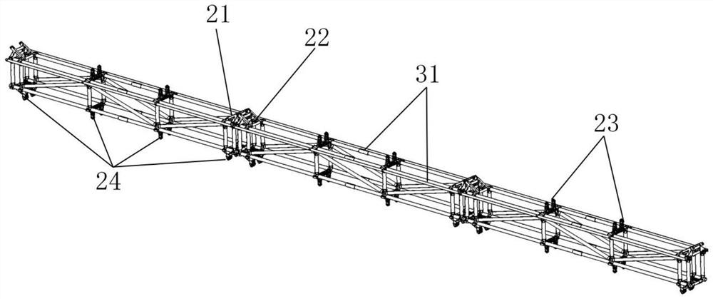
[0043] Please refer to figure 1 , figure 2, figure 1 It is a schematic diagram of the overall structure of a specific embodiment provided by the present invention, figure 2 for figure 1 A schematic diagram of the local structure.

[0044] In a specific embodiment provided by the present invention, the bridge bottom detection operation device mainly includes a load-bearing rope 1 , a track support 2 , an inspection track 3 , an inspection vehicle 4 and a ...


PUM


Abstract

The invention discloses a bridge bottom surface detection operation device. The device comprises a bearing rope which has two ends which are separately hung on the outer walls of the two sides in the width direction of a to-be-detected bridge and is distributed at the bottom of the to-be-detected bridge, a plurality of track supports which are slidably hung on the bearing rope and spliced to form an inspection track, and a plurality of inspection vehicles which are movably arranged on the inspection track and are used for detecting the bottom surface of the to-be-detected bridge, wherein each inspection vehicle is provided with a detection module. Therefore, through splicing of the track supports on the bearing rope, the inspection track is formed at the bottom of the to-be-detected bridge and the inspection vehicles carrying detection modules moves along the inspection track to complete detection operation on the bottom face of the to-be-detected bridge. Due to the fact that the hoisting number of the track supports on the bearing rope is uncertain, the actual hoisting number of the track supports can be flexibly adjusted according to the specific width of the current to-be-detected bridge, the adaptability to bridges with different widths is improved, and detection operation on the bottom face of the bridge can be safely and efficiently achieved.

Description

technical field [0001] The invention relates to the technical field of civil engineering, in particular to a bridge bottom detection operation device. Background technique [0002] Bridge inspection and maintenance is a core issue related to the national economy, the country and the people's security. Regular comprehensive bridge inspections are of great significance for maintaining the safety and normal operation of public transportation. [0003] During the long-term operation of the bridge, due to the influence of water conservancy disasters, collisions, overloads, fatigue and other factors, a series of problems such as structural cracks, deformation, damage, erosion and aging are prone to occur, so it is necessary to regularly inspect the bridge for related items Operation. Due to the suspended structural characteristics of the bridge, the surface of the bridge, the two ends of the bridge, and both sides of the bridge can be easily inspected, but the inspection of the b...

Claims


Application Information

Patent Timeline
IPC IPC(8): E01D19/10
CPCE01D19/106
Inventor 丁宁郝万鈞李德程张爱东
Owner THE CHINESE UNIV OF HONG KONG SHENZHEN
Why Eureka
Eureka Blog
Learn More