Moisture-proof and shock-proof electric appliance and meter placing cabinet convenient to carry and used for power transmission project
A technology for electrical appliances and instruments, which is applied in the field of electrical instrument storage cabinets, can solve the problems of damaged instruments and meters, lack of moisture resistance, etc., and achieve the effect of reducing losses and preventing moisture
- Summary
- Abstract
- Description
- Claims
- Application Information
AI Technical Summary
Problems solved by technology
Method used
Image
Examples
Embodiment 1
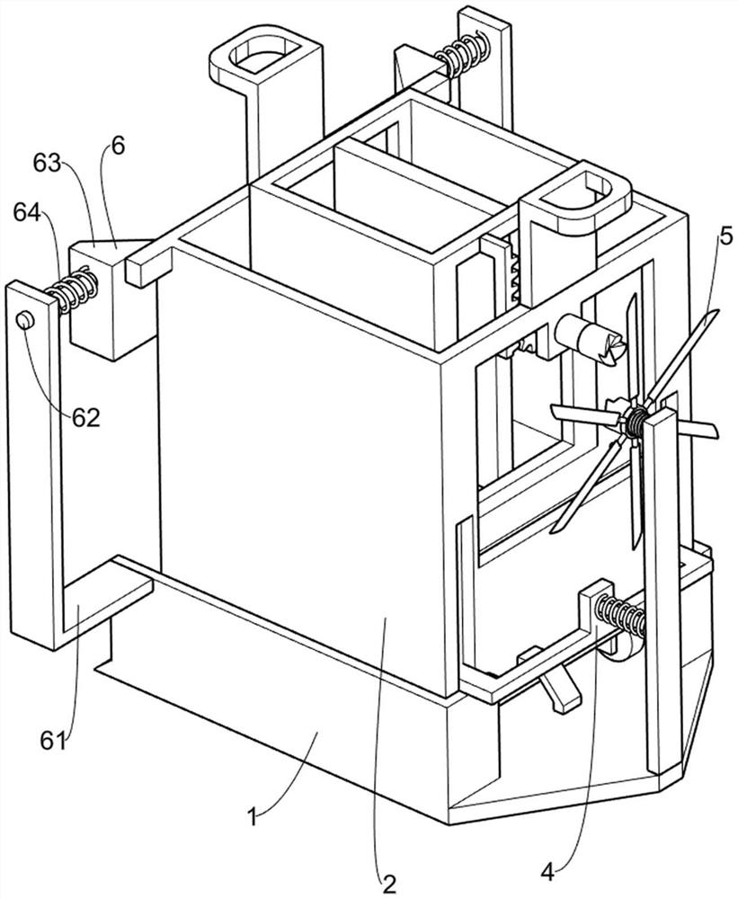
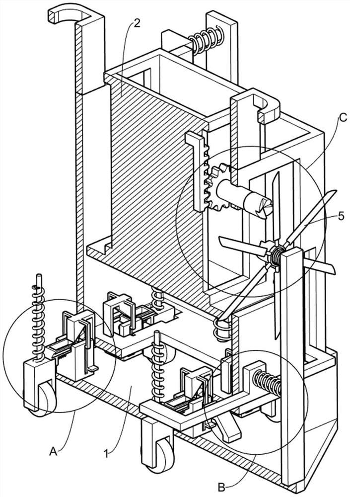
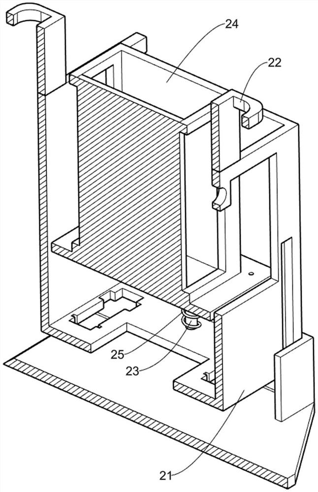
[0025] An electrical instrument storage cabinet that is easy to carry and moisture-proof and shock-proof for power transmission projects, such as Figure 1-6 As shown, it includes a fixed plate 1, an anti-vibration mechanism 2, a rolling mechanism 3 and a first locking mechanism 4. The fixed plate 1 is arranged on other supporting equipment, and the fixed plate 1 is provided with an anti-vibration mechanism 2. The anti-vibration mechanism 2 is used to reduce the For losses caused by vibration, the anti-vibration mechanism 2 is provided with a rolling mechanism 3, which is convenient for personnel to push away the fixed frame 21 and its upper device, and the fixed plate 1 is provided with a first locking mechanism 4.
[0026] The shockproof mechanism 2 includes a fixed frame 21, a handle 22, a first fixed rod 23, a sliding frame 24 and a first return spring 25. The fixed frame 21 is placed on the fixed plate 1, and the top of the fixed frame 21 is symmetrically connected with a ...
Embodiment 2
[0033] On the basis of Example 1, such as Image 6 As shown, blowing mechanism 5 is also included, and blowing mechanism 5 is located on the third fixed frame 41, and blowing mechanism 5 is used to prevent the instrumentation in the sliding frame 24 from getting wet, and blowing mechanism 5 includes rack 51, rotating shaft 52, Gear 53, the first clutch shaft 54, the third fixed rod 55, fan 56, the second clutch shaft 57 and the fifth back spring 58, the upper side of the sliding frame 24 is connected with a rack 51, and the rack 51 is used to drive the gear 53 And the upper device rotates, one side of the fixed frame 21 top is rotatably connected with a rotating shaft 52, one end of the rotating shaft 52 is connected with a gear 53, the gear 53 meshes with the rack 51, and the other end of the rotating shaft 52 is connected with a first clutch shaft 54, The first clutch shaft 54 is used to drive the second clutch shaft 57 and its upper device to reverse, the third fixed fram...
Embodiment 3
[0036] On the basis of Example 2, such as figure 1 As shown, it also includes a second locking mechanism 6, the second locking mechanism 6 is used to prevent the fixed frame 21 and the upper device from shaking at will, the second locking mechanism 6 is located on the fixed plate 1, the second locking mechanism 6 includes a fourth fixed frame 61, a second slide bar 62, a second wedge block 63 and a sixth return spring 64, the fixed plate 1 is symmetrically connected with the fourth fixed frame 61, and the fourth fixed frame 61 is slidably connected with The second slide bar 62, one end of the second slide bar 62 is connected with a second wedge block 63, the second wedge block 63 is used to clamp the fixed frame 21, the second wedge block 63 is in contact with the fixed frame 21, and the second wedge block 63 A sixth return spring 64 is connected between the fourth fixing frame 61, and the sixth return spring 64 is used to drive the second wedge block 63 and its upper device t...
PUM
 Abstract
Description
Claims
Application Information
 - R&D Engineer
- R&D Manager
- IP Professional
- Industry Leading Data Capabilities
- Powerful AI technology
- Patent DNA Extraction
Browse by: Latest US Patents, China's latest patents, Technical Efficacy Thesaurus, Application Domain, Technology Topic, Popular Technical Reports.
© 2024 PatSnap. All rights reserved.Legal|Privacy policy|Modern Slavery Act Transparency Statement|Sitemap|About US| Contact US: help@patsnap.com


