Header for stalk and ear harvesting type corn harvester

A corn harvester and header technology, which is applied to headers, harvesters, applications, etc., can solve the problems of uneven distribution of force and load, easy bending and failure of the intermediate shaft of the header, and inconvenient maintenance and replacement. Small size, reasonable header transmission arrangement and high versatility

Inactive Publication Date: 2021-10-22
河北英虎农业机械股份有限公司
View PDF0 Cites 1 Cited by
  • Summary
  • Abstract
  • Description
  • Claims
  • Application Information

AI Technical Summary

Problems solved by technology

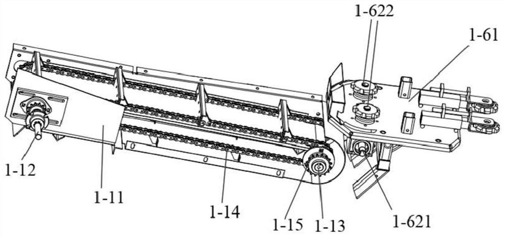
[0002] The feeding method of the rear side of the front cutting knife in the existing stem and ear harvesting platform is a rake chain structure, and its main structure is that a flat tube is installed on the top of the two chains, and the flat tube is dragged by the rotation of the chain to move. Drive the straw backward to achieve the purpose of feeding, but because there are large gaps between adjacent chains and adjacent flat tubes, the straw is easy to fall from the gap, the loss rate is high, and the machine harvesting income drops seriously
[0003] The existing corn harvester header is generally unilaterally driven, and is only transmitted to all moving parts on the entire header through a header intermediate shaft. An intermediate shaft is connected to several ear picking units and also connected to two small liters. The conveyor is also connected with two auger mechanisms and two straw chopping mechanisms. Due to the uneven force and load distribution, the intermediate shaft of the header is easily bent and fails. Because the header space is small and the structure is compact, maintenance and replacement are extremely difficult. inconvenient

Method used


Image

  • Header for stalk and ear harvesting type corn harvester
  • Header for stalk and ear harvesting type corn harvester
  • Header for stalk and ear harvesting type corn harvester

Examples


Embodiment Construction

[0044] In order to make the purpose, technical solutions and advantages of the embodiments of the present invention clearer, the technical solutions in the embodiments of the present invention will be clearly and completely described below in conjunction with the drawings in the embodiments of the present invention. Obviously, the described embodiments It is a part of embodiments of the present invention, but not all embodiments. The components of the embodiments of the invention generally described and illustrated in the figures herein may be arranged and designed in a variety of different configurations.

[0045] Accordingly, the following detailed description of the embodiments of the invention provided in the accompanying drawings is not intended to limit the scope of the claimed invention, but merely represents selected embodiments of the invention. Based on the embodiments of the present invention, all other embodiments obtained by persons of ordinary skill in the art wi...


PUM


Abstract

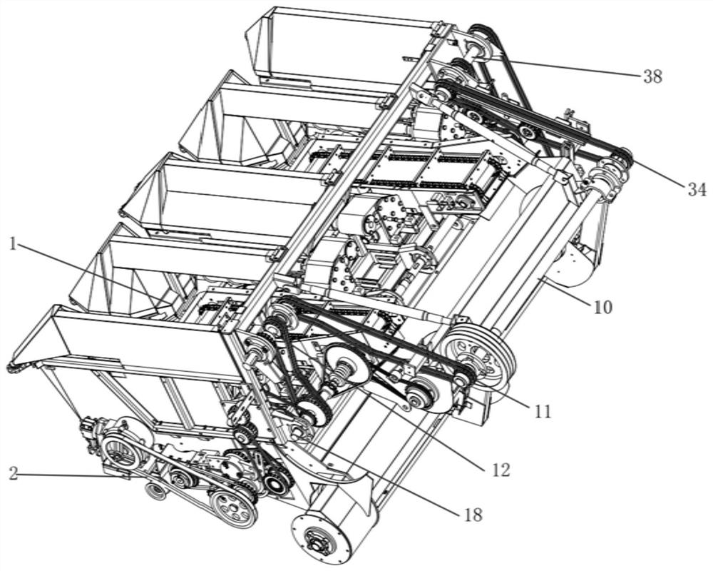
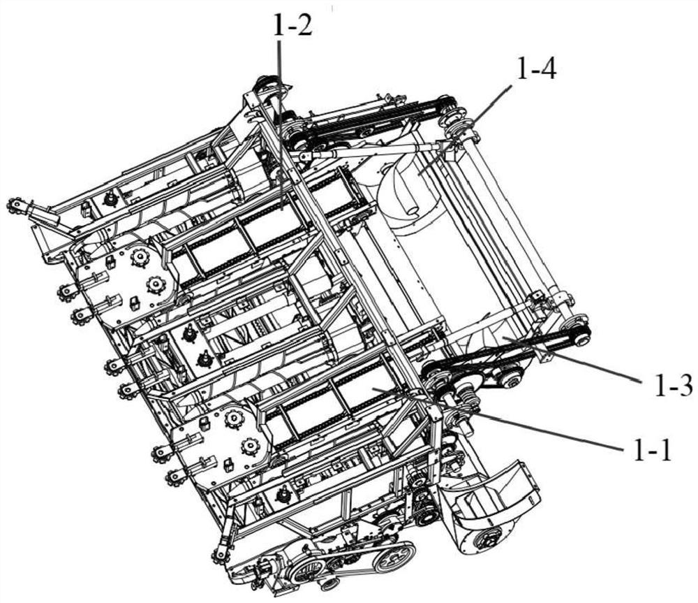
The invention discloses a header for a stalk and ear harvesting type corn harvester. The header comprises an ear harvesting header, a straw harvesting header and a lower main shaft, wherein the ear harvesting header comprises a left small elevator, a right small elevator, a left small auger, a right small auger, a left ear picking mechanism and a right ear picking mechanism; the left ear picking mechanism comprises a first left ear picking unit, a left middle ear picking unit and a second left ear picking unit, and the right ear picking mechanism and the left ear picking mechanism are symmetrically arranged; the first left ear picking unit comprises a first left gearbox, and the second left ear picking unit comprises a second left gearbox; and the left small elevator, the left small auger and the left ear picking mechanism are in transmission connection with a left first shaft of the header, and the right small elevator, the right small auger and the right ear picking mechanism are in transmission connection with a right first shaft of the header. The problems that a transmission chain of an existing header is prone to heating and breaking, a transmission shaft is prone to bending, and transmission reliability of the header is not high are solved, and the header is more reasonable in transmission arrangement, even in load distribution, stable in operation and high in reliability.

Description

technical field [0001] The invention relates to the field of corn harvesters, in particular to a header for a corn harvester with both stem and ear harvesting. Background technique [0002] The feeding method of the rear side of the front cutting knife in the existing stem and ear harvesting platform is a rake chain structure, and its main structure is that a flat tube is installed on the top of the two chains, and the flat tube is dragged by the rotation of the chain to move. Drive the straw backward to achieve the purpose of feeding, but because there are large gaps between adjacent chains and adjacent flat tubes, the straw is easy to fall from the gap, the loss rate is high, and the machine harvesting income drops seriously. [0003] The existing corn harvester header is generally unilaterally driven, and is only transmitted to all moving parts on the entire header through a header intermediate shaft. An intermediate shaft is connected to several ear picking units and als...

Claims


Application Information

Patent Timeline
Patent Type & Authority Applications(China)
IPC IPC(8): A01D47/00A01D45/02A01D43/08A01D69/06A01D57/00
CPCA01D47/00A01D45/021A01D45/025A01D43/086A01D69/06A01D57/00
Inventor 李衡李侠杨香林
Owner 河北英虎农业机械股份有限公司
Why Eureka
Try Eureka