
Railway crossing locomotive detection system based on laser scanning

A technology of laser scanning and detection system, which is applied in the direction of radio wave measurement system, measurement device, electromagnetic wave re-radiation, etc. It can solve the problems of limiting relative distance and relative speed, being unable to accurately identify the detected object, and greatly affecting the perception effect. , to achieve the effect of not easy to interfere, simple installation and high reliability

Pending Publication Date: 2021-10-19
ZHANJIANG PORT (GRP) CO LTD +3
View PDF0 Cites 3 Cited by
  • Summary
  • Abstract
  • Description
  • Claims
  • Application Information

AI Technical Summary

Problems solved by technology

[0007] The object of the present invention is to provide a railway crossing locomotive detection system based on laser scanning, to solve the problem that the controllers of some existing alarm detection systems proposed in the above background technology are relatively complicated and have low reliability. The distance will be affected by some other factors (such as frequency band loss, etc.), and its detection is only limited to measuring the relative distance and relative speed of the target object, so the detected object cannot be accurately identified, and some existing detection systems are It is a passive acceptance of data, and its perception effect is greatly affected by environmental factors, and it cannot solve some key problems

Method used


Image

  • Railway crossing locomotive detection system based on laser scanning
  • Railway crossing locomotive detection system based on laser scanning

Examples


Embodiment 1

[0036] Railway crossing detection data initialization

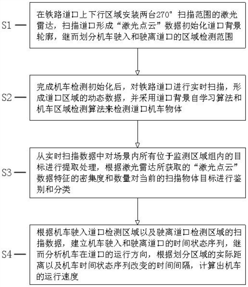
[0037] The area group is used to describe the locomotive data within the coverage of each area. The crossing locomotive area monitoring function is based on the work of the area group, and the shape area that needs to be scanned by the lidar at the railway crossing is custom drawn, and the area is adjusted according to the on-site working conditions of the railway crossing. The shape is adjusted and the edges are refined to obtain the desired region group. The area division adopts the expression of "depth range", and the main data of its data structure includes the starting angle θ of the area scanning angle k,0 and termination angle θ k,n , the depth range includes the start depth and the end depth, which represent the range of the ray segment distance of the area at the scan angle. The depth measurement data at the scan angle only belong to this area when it is within this range, and the area group is completed. After...


PUM


Abstract

A railway crossing locomotive detection system based on laser scanning disclosed by the invention comprises a system and a laser radar. The system is composed of the laser radar and a locomotive detection algorithm, the laser radar is installed in a railway crossing area, then the area detection range is divided, and the railway crossing is scanned in real time to form dynamic data. A crossing background self-learning algorithm and a locomotive area detection algorithm are adopted to detect crossing locomotive objects, then targets in a scene are extracted from real-time scanning data, the current scanned locomotive objects are identified and classified, and a time state data sequence of the locomotive entering and leaving the crossing is established according to the scanning data; and finally, the running speed of the locomotive is calculated. According to the invention, the problems of few locomotive detection methods, poor detection stability and incomplete functions under the current complex background of the railway crossing are effectively solved, support is provided for full-automatic safe operation of the unmanned railway crossing, and the intelligent level of safety supervision of the railway crossing is further improved.

Description

technical field [0001] The invention relates to the technical field of port railway traffic intelligent supervision, in particular to a laser scanning-based railway crossing locomotive detection system. Background technique [0002] Most of the detection systems of short-distance vehicle intrusion alarm detection technology at modern railway crossings in my country have simple control logic and require a lot of manpower and material resources to participate in manual control throughout the entire process. For the research on railway crossing detection, the earliest method used is the track circuit , due to the many shortcomings of the track circuit, such as single function, easy to report errors, and a large amount of installation tasks, the embedded monitoring system based on infrared sensing technology was subsequently developed, but the detection accuracy of this technology is limited, and because the sensor The difference in height will affect the final result, so it is no...

Claims


Application Information

Patent Timeline
IPC IPC(8): G01S17/88G01S17/04G01S17/08G01S17/58
CPCG01S17/88G01S17/04G01S17/08G01S17/58
Inventor 李建军谢兆青蔺佰文刘清周平窦琴任洪森颜明李新王昊丹黄章才高伟刚
Owner ZHANJIANG PORT (GRP) CO LTD
Learn More