Valve driving device and method of engine
A driving device and engine technology, which is applied in the direction of engine components, machines/engines, valve devices, etc., can solve the problems of changing the layout of the engine valve mechanism, adding additional parts, complex structure, etc., to achieve good cold start performance at idle speed and ensure stability Sex, good effect
- Summary
- Abstract
- Description
- Claims
- Application Information
AI Technical Summary
Problems solved by technology
Method used
Image

Examples
Embodiment 1
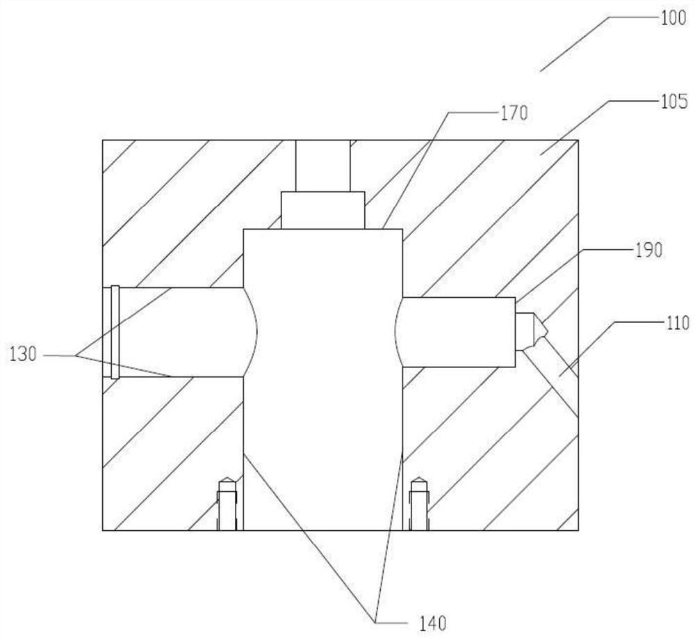
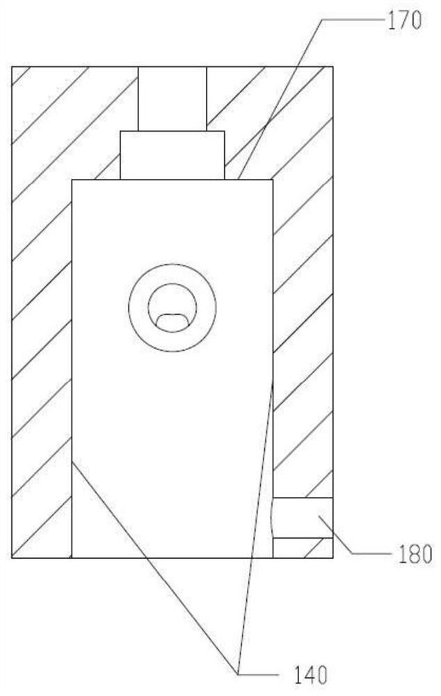
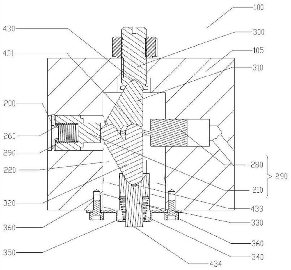
[0060] Such as image 3 As shown, the engine valve driving device 100 of the present invention includes a casing 105, connecting rods (upper connecting rod 310 and lower connecting rod 320) and a working piston 330, and a drive reset assembly 290 (the drive reset device here has a drive piston 280 and reset piston 210 form). Such as figure 1 with 2 As shown, the box body 105 is a rocker arm, and the rocker arm is assembled on the rocker arm shaft (not shown) of the engine through the rocker arm hole (not shown); the box body 105 is provided with a vertical channel 140 and a horizontal channel 130 that vertically intersect. The oil channel 110 and the assembly step 170 (located on the vertical channel 140 ), the bottom 190 and the positioning hole 180 of the horizontal channel 130 .
[0061] Such as image 3 As shown, the vertical passage 140 is provided with an upper connecting rod 310, a lower connecting rod 320, and a limit block 220; The lower end of the upper connecti...
Embodiment 2
[0078] Such as Figure 11 As shown, the engine valve driving device 100 of this embodiment is a modification of Embodiment 1, including a box body 105 ( figure 1 , the box shown is the rocker arm, the rocker arm is assembled on the rocker arm shaft (not shown) of the engine through the rocker arm hole (not shown), the upper link 310 and the lower link 320, the working piston 330 and the drive reset Assembly 290 (the drive reset assembly here has elephant foot 280, and ball pin 288 and pin 282 form). The casing 105 is provided with a vertical passage 140 and a horizontal passage 130 (see figure 1 ).
[0079] Such as Figure 11 As shown, the vertical passage 140 is provided with an upper connecting rod 310 , a lower connecting rod 3201 , and a limit block 220 ; the upper end of the vertical passage 140 is provided with an adjusting bolt 300 , and the lower end is provided with a working piston 330 and a compression spring 340 . The lower connecting rod 3201 is V-shaped, wher...
Embodiment 3
[0095] Such as Figure 16 As shown, the engine valve driving device 100 of this embodiment is a modification of Embodiment 1, including a box body 105 ( figure 1 , the box shown is the rocker arm, the rocker arm is assembled on the rocker arm shaft (not shown) of the engine through the rocker arm hole (not shown), the upper link 310 and the lower link 320, the working piston 330 and the drive reset Component 290 (as Figure 13 with 14 As can be seen, the drive reset assembly here consists of a piston 2822, a locking bolt 283 and a push-pull rod 2882). The casing 105 is provided with a vertical passage 140 and a horizontal passage 130 (see figure 1 ).
[0096]An upper connecting rod 310 and a lower connecting rod 320 are arranged in the vertical passage, a limit block 220 is arranged in the vertical passage 140 , and a working piston 330 is arranged at the lower end. The horizontal channel 130 is provided with a drive reset assembly 290 , a reset spring 270 and a positioni...
PUM
 Abstract
Description
Claims
Application Information
 - R&D
- Intellectual Property
- Life Sciences
- Materials
- Tech Scout
- Unparalleled Data Quality
- Higher Quality Content
- 60% Fewer Hallucinations
Browse by: Latest US Patents, China's latest patents, Technical Efficacy Thesaurus, Application Domain, Technology Topic, Popular Technical Reports.
© 2025 PatSnap. All rights reserved.Legal|Privacy policy|Modern Slavery Act Transparency Statement|Sitemap|About US| Contact US: help@patsnap.com