Split type floor and production method thereof

A split-type, floor technology, applied in the direction of floors, buildings, building structures, etc., can solve the problems of troublesome floor removal, easy damage to floor heating and various pipes, time-consuming and labor-intensive, etc., to achieve fast replacement operations and simple paving. Convenient and fast effects

Pending Publication Date: 2021-10-15
郑素梅
View PDF5 Cites 0 Cited by
  • Summary
  • Abstract
  • Description
  • Claims
  • Application Information

AI Technical Summary

Problems solved by technology

[0002] In the prior art, each floor is an integrated board, such as single-layer structure tiles and composite floors with multiple structural layers of different materials, all of which are composite and inseparable boards. After the floor is installed on the ground , if you need to replace the floor, you need to remove the original floor first, re-treat the ground to make it meet the paving conditions, and finally pave the new floor. The floor removal needs to bond the entire floor to the bottom of the floor during the paving process If the bonding material layer is scraped off, the demolition of the floor is very troublesome, time-consuming and labor-intensive, especially if the floor heating and various pipes are installed on the bottom of the floor, it is very easy to damage the floor heating and various pipes installed under the floor during the removal process , so it is necessary to improve

Method used


Image

  • Split type floor and production method thereof
  • Split type floor and production method thereof
  • Split type floor and production method thereof

Examples


Embodiment 1

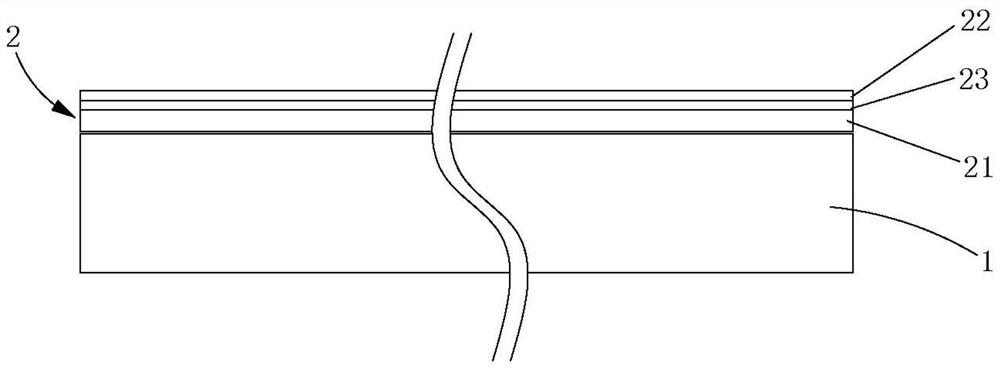
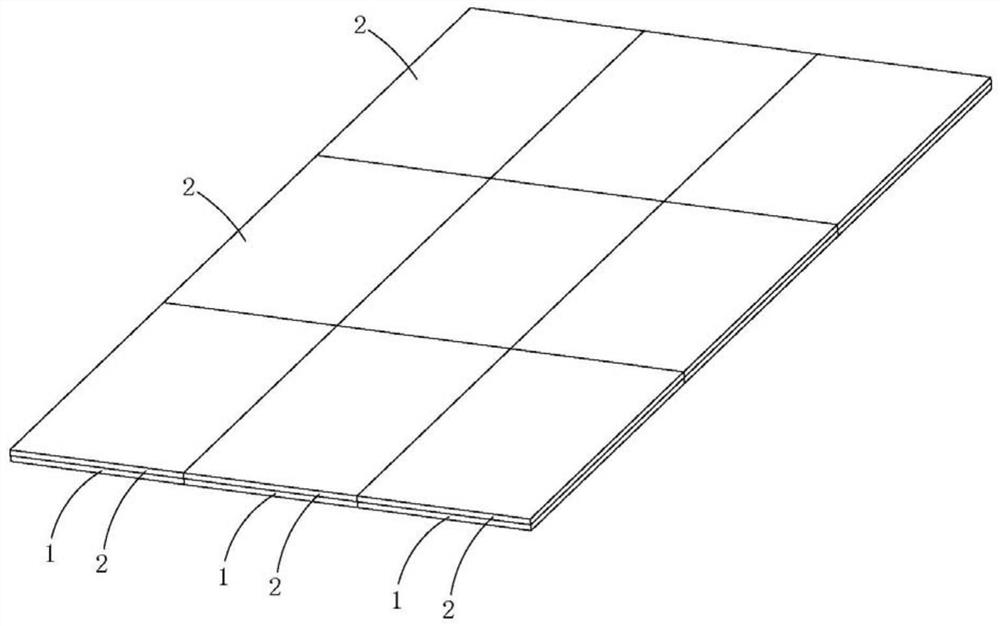
[0046] a split floor, Figures 1 to 4As shown, it includes a split base plate 1 for paving and fixing on the ground and a split decorative panel 2 that is independently set apart from the split base plate 1. The top surface of the split base plate 1 is set to be used for paving the split decorative panel. 2, the top surface of the split bottom plate 1 is a flat and smooth plane, the bottom surface of the split decorative panel 2 is compounded with a self-priming medium layer 21, and the split decorative panel 2 is paved and fixed on the split-type decorative panel 2 through the self-priming medium layer 21. The top surface of base plate 1.

[0047] The split decorative panel 2 comprises a panel base material 23 and a surface wear-resistant layer 22 compounded on the top surface of the panel base material 23, and the surface wear-resistant layer 22 comprises a pattern layer compounded on the top surface of the panel base material 23 and a pattern layer compounded on the pattern...

Embodiment 2

[0065] A production method of a split floor, Figures 1 to 3 shown, including the following steps,

[0066] In the plate production step, respectively produce the split bottom plate 1 whose size and specification is a large plate specification and the split decorative panel 2 whose size and specification are a large plate specification as described in Embodiment 1;

[0067] Large-slab compounding step, absorbing or adhering the split-type decorative panel 2 of the large-slab specification to the surface of the split-type bottom plate 1 of the same size specification to obtain a split-type floor slab whose size specification is the large-slab specification;

[0068] The slab cutting step is to cut the split floor slab into a finished split floor whose size is equal to or close to that of the finished split floor;

[0069] The post-processing step is to carry out post-processing treatment. The post-processing treatment includes at least one of groove forming processing, mechani...

Embodiment 3

[0073] A production method of a split floor, Figures 1 to 4 shown, including the following steps,

[0074] In the plate production step, respectively produce the split bottom plate 1 whose size and specification is a large plate specification and the split decorative panel 2 whose size and specification are a large plate specification as described in Embodiment 1;

[0075] The large-slab cutting step is to cut the split floor 1 of the large-slab specification and the split-type decorative panel 2 of the large-slab specification into sub-slabs and surface layers whose dimensions are equal to or close to those of the finished split floor plate small plate;

[0076] The post-processing step is to carry out post-processing treatment on the small board of the bottom layer or the small board of the surface layer. The post-processing treatment includes at least one of the groove and tenon forming processing, mechanical trimming processing and maintenance treatment. The groove and t...


PUM

PropertyMeasurementUnit
thicknessaaaaaaaaaa

Abstract

The invention discloses a split type floor and a production method thereof. The split type floor comprises split type bottom plates and split type decoration panels which are fixedly laid on the ground, the top surfaces of the split type bottom plates are arranged to be planes for laying the split type decoration panels, self-adhesion medium layers are compounded on the bottom surfaces of the split type decoration panels, and the split type decoration panels are fixedly laid on the top surfaces of the split type bottom plates through the self-adhesion medium layers. In the floor laying process, the split type floor can be laid in a traditional floor laying mode, or all the split type bottom plates can be fixedly laid on the ground firstly, and then all the split type decoration panels are movably attached to or bonded to the top surfaces of the split type bottom plates one by one and spliced one by one. When the floor needs to be replaced, only the original split type decoration panels need to be detached firstly, and then new split type decoration panels are laid again, so that the replacement operation of the floor is quicker, simpler and more convenient, and time, labor and money are saved on.

Description

technical field [0001] The invention relates to the technical field of composite floors, in particular to a split floor and a production method thereof. Background technique [0002] In the prior art, each floor is an integrated board, such as single-layer structure tiles and composite floors with multiple structural layers of different materials, all of which are composite and inseparable boards. After the floor is installed on the ground , if you need to replace the floor, you need to remove the original floor first, re-treat the ground to make it meet the paving conditions, and finally pave the new floor. The floor removal needs to bond the entire floor to the bottom of the floor during the paving process If the bonding material layer is scraped off, the demolition of the floor is very troublesome, time-consuming and labor-intensive, especially if the floor heating and various pipes are installed on the bottom of the floor, it is very easy to damage the floor heating and ...

Claims


Application Information

Patent Timeline
Patent Type & Authority Applications(China)
IPC IPC(8): E04F15/02
CPCE04F15/02E04F15/02038E04F15/087E04F15/107E04F15/102E04F15/105E04F15/0215E04F2201/04
Inventor 郑素梅戴东锡
Owner 郑素梅
Why Eureka
Try Eureka