
A plastic edge banding cutting device

A shearing device and plastic sealing technology, applied in metal processing and other directions, can solve problems such as uneven shearing surface

Active Publication Date: 2021-11-26
江苏钜瀚塑胶制品有限公司
View PDF0 Cites 0 Cited by
  • Summary
  • Abstract
  • Description
  • Claims
  • Application Information

AI Technical Summary

Problems solved by technology

[0005] The purpose of the present invention is to provide a plastic edge band shearing device, aiming to solve the problem that the end of the plastic edge band protruding from the operating table will drop under the action of gravity, resulting in an uneven shearing surface

Method used

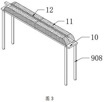

Image

  • A plastic edge banding cutting device
  • A plastic edge banding cutting device
  • A plastic edge banding cutting device

Examples


Embodiment Construction

[0032] In order to make the object, technical solution and advantages of the present invention clearer, the present invention will be further described in detail below in conjunction with the accompanying drawings and embodiments. It should be understood that the specific embodiments described here are only used to explain the present invention, not to limit the present invention.

[0033] The specific implementation of the present invention will be described in detail below in conjunction with specific embodiments.

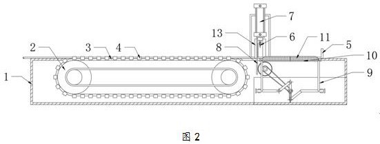
[0034] Such as figure 2 As shown, it is a structural diagram of a plastic edge strip shearing device provided by an embodiment of the present invention, including:

[0035] console 1;

[0036] There are two conveying wheels 2, both of which are rotatably installed in the console 1. One of the conveying wheels 2 is driven to rotate by an external power source, and the two conveying wheels 2 rotate synchronously to drive the conveyor belt 3 to transport Plastic...


PUM


Abstract

The present invention is applicable to the technical field of plastic edge banding processing, and provides a plastic edge banding shearing device, the device comprising: an operating table; a conveying wheel; a shearing device; a closing plate; an opening and closing assembly; and a transmission assembly; By sliding and installing two closing plates on the operating table, it is used to close the drop position before the shearing is completed, so as to avoid the plastic edge banding from falling during the shearing process. After the shearing is completed, the shearing device rises and is driven by the transmission assembly. Open and close the assembly, so that the two closed plates are separated, and the plastic edge strips cut off at the drop position will fall into the collection box in the operation table. Close up and close to each other, effectively avoiding the problem that the end of the plastic edge banding will drop under the action of gravity and cause the deformation of the shear end, which will affect the flatness of the shear surface.

Description

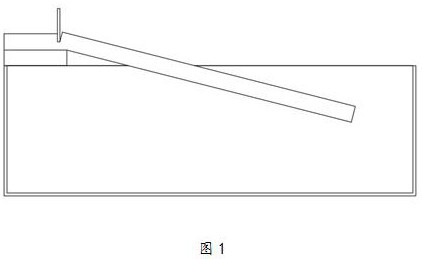
technical field [0001] The invention belongs to the technical field of plastic edge banding processing, and in particular relates to a plastic edge banding shearing device. Background technique [0002] The plastic edge banding is formed by a plastic molding machine, and after forming, it needs to be cut into sections of plastic edge banding with a fixed size. [0003] During the manufacturing process, the plastic edge banding needs to be conveyed by the conveying device, and then cut section by section. At present, such as figure 1 In the way shown, the plastic edge banding is transported by the conveyor belt until one end of the plastic edge banding protrudes from the edge of the operating table, and the shearing equipment is started to cut it. After the cutting is completed, the plastic edge protruding from the edge of the operating table The edgebands fall under the force of gravity and are collected. [0004] However, in the existing shearing and collecting method of ...

Claims


Application Information

Patent Timeline
Patent Type & Authority Patents(China)
IPC IPC(8): B26D7/32
CPCB26D7/32
Inventor 施懿施业瑛
Owner 江苏钜瀚塑胶制品有限公司
Learn More