High-precision bearing retainer blanking shape precise reconstruction equipment
A bearing cage, high-precision technology, used in bearing components, shafts and bearings, mechanical equipment, etc., can solve the problems of restricted exports, bearing cages cannot meet high-precision bearings, and accuracy indicators cannot meet some applications.
- Summary
- Abstract
- Description
- Claims
- Application Information
AI Technical Summary
Problems solved by technology
Method used
Image
Examples
Embodiment 1
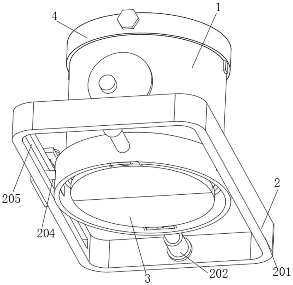
[0042] Please refer to Figure 1-8 As shown, a high-precision bearing cage blanking shape accurate reconstruction equipment, including the dropping device 1, also includes:
[0043] Fixedly set the blocking device 3 on the outer surface of the bottom of the dropping device 1;
[0044] The mobile device 2 fixedly installed on the outside of the blocking device 3;
[0045] The clamping block 4 connected to the top of the dropping device 1 is fixed by bolts;
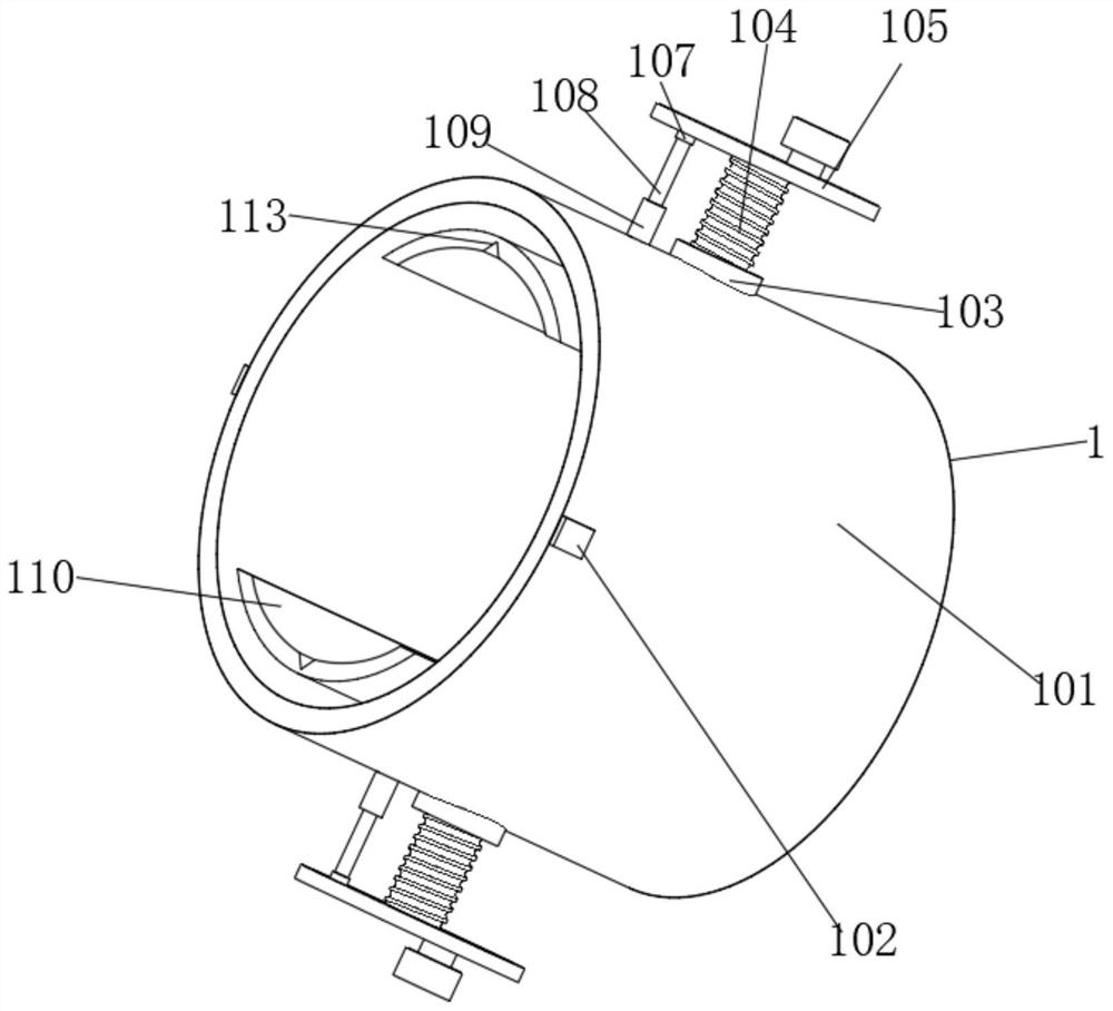
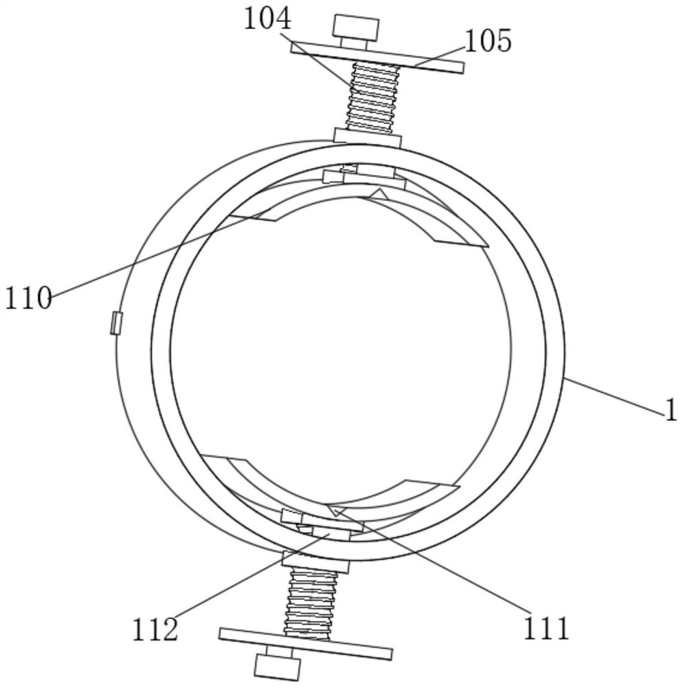
[0046] The dropping device 1 includes a cylinder body 101. Positioning blocks 102 are fixedly installed on both sides of the top of the outer surface of the cylinder body 101, and transverse nuts 103 are welded on both sides of the cylinder body 101, and the inner walls of the two transverse nuts 103 are screwed together. There are screw rods 104, and the ends of the two screw rods 104 away from the cylinder body 101 are fixedly equipped with handwheels 105, and the sides of the two handwheels 105 close to the cylinder bo...
Embodiment 2
[0049] On the basis of Example 1, please refer to figure 1 and Figure 5 As shown, the mobile device 2 includes a fixed ring 203 fixedly sleeved on the outer surface of the cylinder body 101. Electric telescopic rods 202 are fixedly installed on both sides of the outer surface of the fixed ring 203, and the outer sides of the two electric telescopic rods 202 are fixedly installed with supports. Frame 201, the both sides of support frame 201 inner walls are all provided with draw-in groove 205, the inside of two draw-in grooves 205 all slidingly connects limit block 204, the rear surface of rear side limit block 204 is fixedly installed with device frame 206, device frame The top of 206 is welded with vertical nut 209, and the internal thread of vertical nut 209 is connected with screw mandrel 208, and the top of screw mandrel 208 is fixedly installed with turntable 207, and the bottom of screw mandrel 208 is connected with splint 211 through rotating shaft 210 rotation, and re...
Embodiment 3
[0052] On the basis of Example 1, please refer to figure 1 and Figure 6 As shown, the blocking device 3 includes an insert ring 301 fixedly sleeved on the bottom of the outer surface of the cylinder body 101, and both sides of the inner wall of the insert ring 301 are fixedly equipped with a fixing frame 302, and the inside of the fixing frame 302 is connected with a rotating rod 303 through a rotating rod 303. Rotating block 305, one side of rotating block 305 is rotatably connected with fan-shaped plate 306, the outer surface of rotating rod 303 is covered with torsion spring 304, one side of torsion spring 304 is fixedly welded on one side of rotating block 305, and torsion spring 304 The other end is welded on one side of the fixed frame 302 inner wall.
[0053] When blanking, the material is on the top of the material blocking device 3, and the material itself has weight, and the weight of the material drives the fan-shaped plate 306 to rotate inside the fixed frame 302...
PUM
 Abstract
Description
Claims
Application Information
 - R&D Engineer
- R&D Manager
- IP Professional
- Industry Leading Data Capabilities
- Powerful AI technology
- Patent DNA Extraction
Browse by: Latest US Patents, China's latest patents, Technical Efficacy Thesaurus, Application Domain, Technology Topic, Popular Technical Reports.
© 2024 PatSnap. All rights reserved.Legal|Privacy policy|Modern Slavery Act Transparency Statement|Sitemap|About US| Contact US: help@patsnap.com


