Fire fighting device based on Internet of Things and operation method thereof
A technology of fire extinguisher and Internet of Things, which is applied in fire rescue and other fields, and can solve the problem of lack of active fire extinguishing function of the device
- Summary
- Abstract
- Description
- Claims
- Application Information
AI Technical Summary
Problems solved by technology
Method used
Image
Examples
Embodiment 1
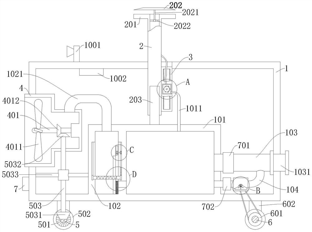
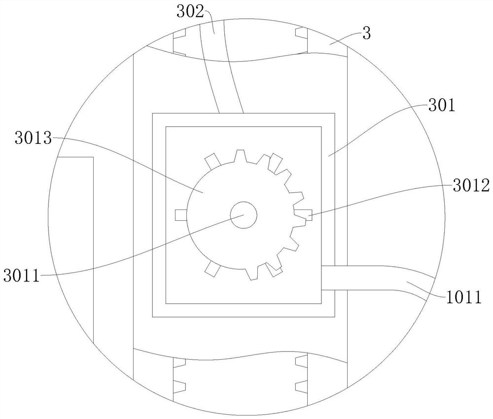
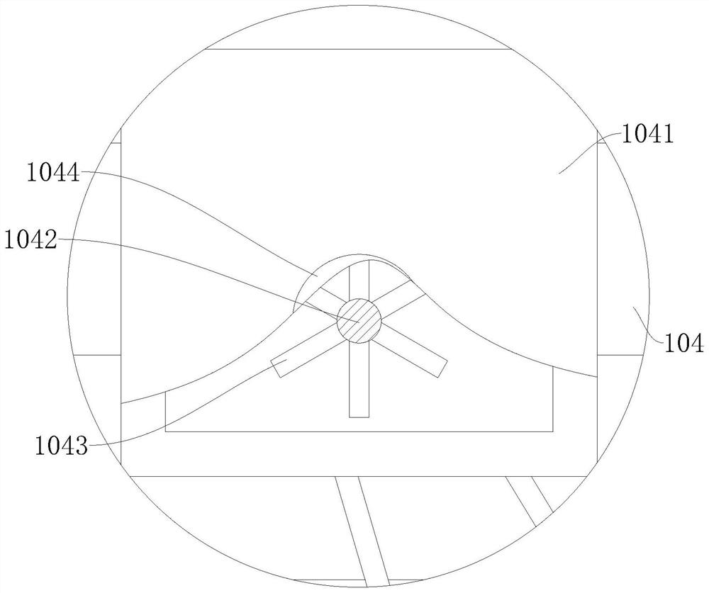
[0035] refer to Figure 1-6 , a fire extinguisher based on the Internet of Things, including a box body 1, a water tank 101 is fixedly connected in the box body 1, a dust collection box 102 is fixedly connected to the water tank 101, and a first water receiving pipe 103 and a second water receiving pipe 103 are fixedly connected to the water tank 101. The water receiving pipe 104, the first water receiving pipe 103 is fixedly connected with the installation ring 1031, the installation ring 1031 is fixedly connected on the box body 1, the second water receiving pipe 104 is fixedly connected on the first water receiving pipe 103, and the second water receiving pipe 104 is fixed A first driving box 1041 is connected, and a first driving shaft 1042 is connected in rotation in the first driving box 1041. A first driving plate 1043 and a first pulley 1044 are fixedly connected to the first driving shaft 1042, and the first driving plate 1043 rotates. Connected in the first driving b...
Embodiment 2
[0037] refer to Figure 1-6 , is basically the same as that of Embodiment 1, furthermore, a dust collecting cover 4 is fixedly connected to the box body 1, a third rotating shaft 401 is rotatably connected in the dust collecting cover 4, and a blade 4011 is fixedly connected to the third rotating shaft 401, and the blade 4011 4011 is rotatably connected in the dust collecting cover 4, the second rotating shaft 5 is fixedly connected with the first gear 501, the inside of the box 1 is rotatably connected with the fourth rotating shaft 503, and one end of the fourth rotating shaft 503 is fixedly connected with the second gear 5031, the second The other end of the four rotating shafts 503 is fixedly connected with a third gear 5032, the first gear 501 meshes with the second gear 5031, the third rotating shaft 401 is fixedly connected with a fourth gear 4012, the third gear 5032 meshes with the fourth gear 4012, and the box The body 1 is fixedly connected with the first mounting f...
Embodiment 3
[0039] refer to Figure 1-6 , is basically the same as Embodiment 1, furthermore, the dust collection box 102 is fixedly connected with a mounting bar 1026, the blocking plate 8 is slidably connected in the mounting bar 1026, and the dust collecting hood 4 is fixedly connected with a connecting pipe 1021, and the connecting pipe 1021 is fixedly connected to the dust collection box 102, the top of the water spray pipe 2 is fixedly connected with a circular plate 201 and a circular plate 202, the centers of the circular plate 201 and the circular plate 202 are located on the same axis, and the water spray pipe 2 is fixedly connected There is a second mounting frame 2022 , and a mounting rod 2021 is fixedly connected to the second mounting frame 2022 , and the circular plate 202 is fixedly connected to the mounting rod 2021 .
[0040] A method for using a fire extinguisher based on the Internet of Things, comprising the following steps:
[0041] S1: Adjust the running direction ...
PUM
 Abstract
Description
Claims
Application Information
 - R&D
- Intellectual Property
- Life Sciences
- Materials
- Tech Scout
- Unparalleled Data Quality
- Higher Quality Content
- 60% Fewer Hallucinations
Browse by: Latest US Patents, China's latest patents, Technical Efficacy Thesaurus, Application Domain, Technology Topic, Popular Technical Reports.
© 2025 PatSnap. All rights reserved.Legal|Privacy policy|Modern Slavery Act Transparency Statement|Sitemap|About US| Contact US: help@patsnap.com


