Pressure-displacement cooperative control stationary shoulder friction stir welding spindle head device

A friction stir welding and static shoulder technology, which is applied in welding equipment, manufacturing tools, non-electric welding equipment, etc., can solve problems such as unstable welding process, achieve compact structure, stable static process, and improve rigidity and stability.

Pending Publication Date: 2021-10-12
天津益普科技发展有限公司
View PDF0 Cites 0 Cited by
  • Summary
  • Abstract
  • Description
  • Claims
  • Application Information

AI Technical Summary

Problems solved by technology

[0006] The invention overcomes the deficiencies in the prior art. The existing main welding head device has problems such as unstable welding process and incomplete penetration of the root, and provides a pressure-displacement cooperative control static shoulder friction stir welding spindle head device. The device realizes the full penetration of the friction stir welding seam, and the static process is stable. At the same time, the device has the advantages of compact structure and flexibility.

Method used


Image

  • Pressure-displacement cooperative control stationary shoulder friction stir welding spindle head device
  • Pressure-displacement cooperative control stationary shoulder friction stir welding spindle head device

Examples


Embodiment 1

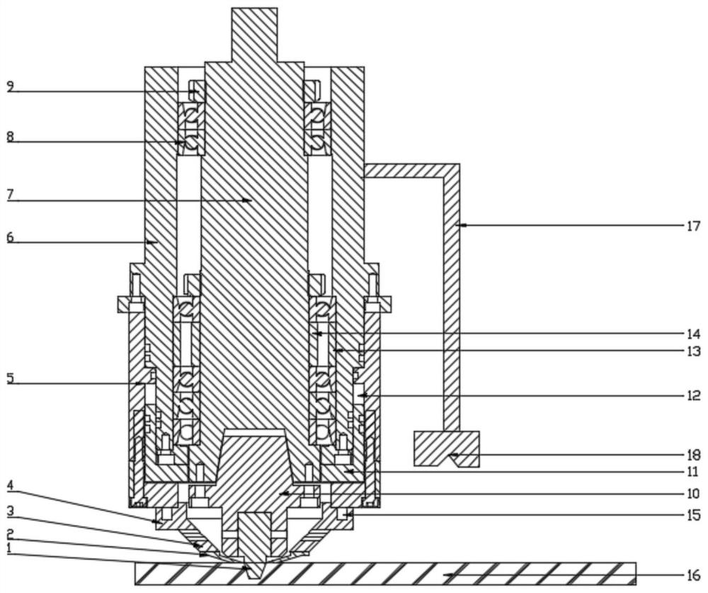
[0027] A pressure-displacement cooperative control static shoulder friction stir welding spindle head device, including a clamping system, a hydraulic system and a static shoulder system,

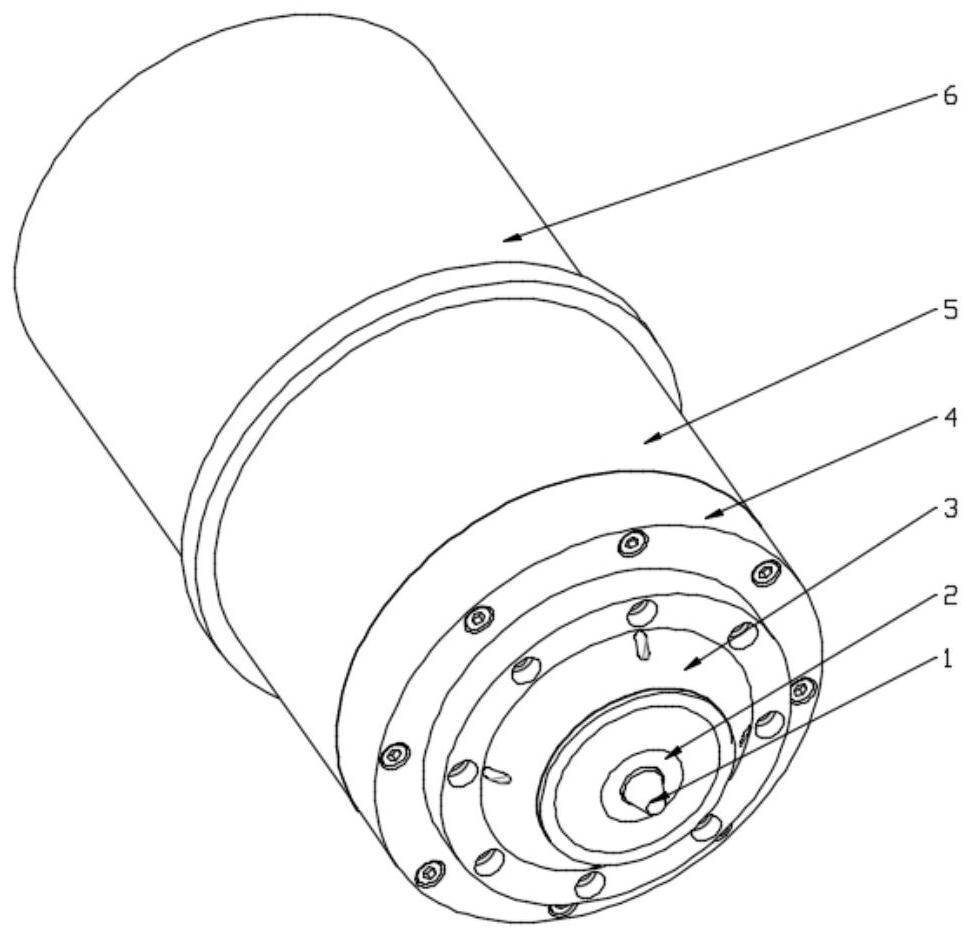
[0028] The clamping system includes a housing 6, a rotating shaft 7, a knife handle 10 and a stirring needle 1. The housing 6 adopts a hollow structure, and the rotating shaft 7 is arranged in the housing 6 through a bearing group 8. The first end of pin 1 is connected;

[0029] The hydraulic system includes an outer piston 5, an oil chamber 12 and an oil seal cover 11. The outer piston 5 is connected with the lower part of the housing 6 through a guide key. The outer piston 5 moves up and down along the outer wall of the housing 6. The oil seal cover 11 and the tail of the housing 6 The ends are fixedly connected, the oil seal cover 11 adopts a hollow structure, and an oil chamber 12 is formed between the outer piston 5, the housing 6 and the oil seal cover 11, and the oil chamber 12 is us...

Embodiment 2

[0032] On the basis of Embodiment 1, the spindle head device also includes a support frame 17 and a displacement sensor 18. The head end of the support frame 17 is fixedly connected to the outside of the housing 6, and the tail end of the support frame 17 is connected to the displacement sensor 18. The displacement sensor 18 is used to detect the plate thickness change of the workpiece 16 to be welded in real time and send the data to the control system for real-time adjustment, and the control system then controls the hydraulic system to adjust its output pressure, that is, the outer piston 5 moves to drive the stationary shoulder system to move, In order to achieve the purpose of real-time control of the axial displacement of the stirring needle 1.

Embodiment 3

[0034] On the basis of Embodiment 2, the number of bearing groups 8 is 2 groups, and the bearing groups 8 are respectively arranged in groups along the rotating shaft 7 from top to bottom. The lower bearing set 8 has four bearings.

[0035] The bearing adopts angular contact bearing.

[0036] An outer spacer 13 and an inner spacer 14 are sequentially arranged between adjacent bearings, and a tight locking nut 9 for fixing the bearing is arranged at the rear end of the rearmost bearing.


PUM


Abstract

The invention provides a pressure-displacement cooperative control stationary shoulder friction stir welding spindle head device. The device is characterized in that a shell is of a hollow structure, a rotating shaft is arranged in the shell through a bearing pack, and the tail end of the rotating shaft is connected with the head end of a welding pin through a cutter handle; an outer piston is connected with the lower portion of the shell, an oil seal cover is fixedly connected with the tail end of the shell, the oil seal cover is of a hollow structure, and an oil cavity is formed among the outer piston, the shell and the oil seal cover; and a shoulder fixing ring is fixedly connected with the bottom of the outer piston, a shoulder transition ring is connected with a static shoulder through the shoulder fixing ring, and the welding pin penetrates through the static shoulder and extends out of the static shoulder. The device realizes full penetration of a friction stir welding seam, is stable in static process, and has the advantages of compact structure, flexibility and the like.

Description

technical field [0001] The invention relates to the technical field of friction stir welding, in particular to a pressure-displacement cooperative control static shoulder friction stir welding spindle head device. Background technique [0002] Since the friction stir welding (FSW) technology was invented by the British Welding Institute (TWI) in 1991, it has been widely used in the connection of light metal alloys such as aluminum alloys and magnesium alloys due to its advantages of high quality welded joints, high degree of automation, green and pollution-free. Stirring head is an important component of friction stir welding equipment and the core of friction stir welding technology. The stirring head is composed of a shaft shoulder, a stirring needle, and a holding part of the stirring head. [0003] During the friction stir welding process, the stirring pin rotates to generate welding heat, and drives the material flow around the stirring pin to form a welded joint; on t...

Claims


Application Information

Patent Timeline
Patent Type & Authority Applications(China)
IPC IPC(8): B23K20/12
CPCB23K20/1245B23K20/123
Inventor 王旭彤李京鹏刘伟
Owner 天津益普科技发展有限公司
Why Eureka
Try Eureka