Eureka AIR delivers breakthrough ideas for toughest innovation challenges, trusted by R&D personnel around the world.

Transformer substation automatic control lightning protection and lightning triggering system

A substation and lightning protection technology, applied in wind power generation, electrical components, cable installation, etc., can solve the problems of limited lightning range of lightning protection device, poor effect of lightning protection and lightning induction, and inability to move lightning protection device, so as to increase the range of activities and wide range , The effect of convenient loading and unloading

Active Publication Date: 2021-10-08
ZHENGZHOU UNIV OF IND TECH
View PDF14 Cites 0 Cited by
  • Summary
  • Abstract
  • Description
  • Claims
  • Application Information

AI Technical Summary

Problems solved by technology

[0003] In the prior art, most of the lightning protection devices are fixed in a specific place, resulting in the inability of the lightning protection device to move, so that the range of lightning received by the lightning protection device is limited, resulting in a poor effect of lightning protection and induction
However, conventional lightning protection settings cannot completely cover the angle of lightning strikes. Therefore, how to protect the various electrical facilities in the substation under heavy lightning weather requires better devices to solve the above problems.

Method used


Image

  • Transformer substation automatic control lightning protection and lightning triggering system
  • Transformer substation automatic control lightning protection and lightning triggering system
  • Transformer substation automatic control lightning protection and lightning triggering system

Examples


Embodiment

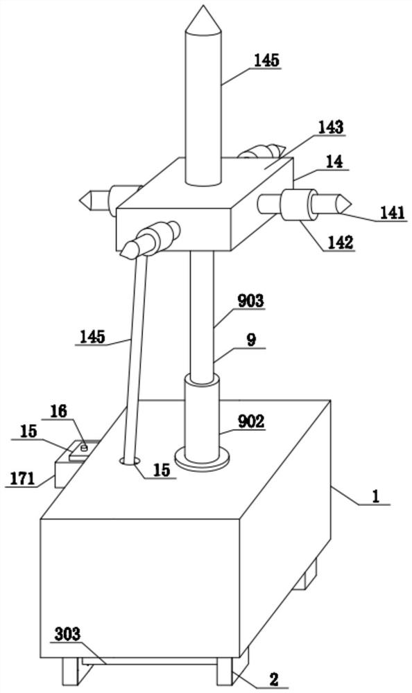
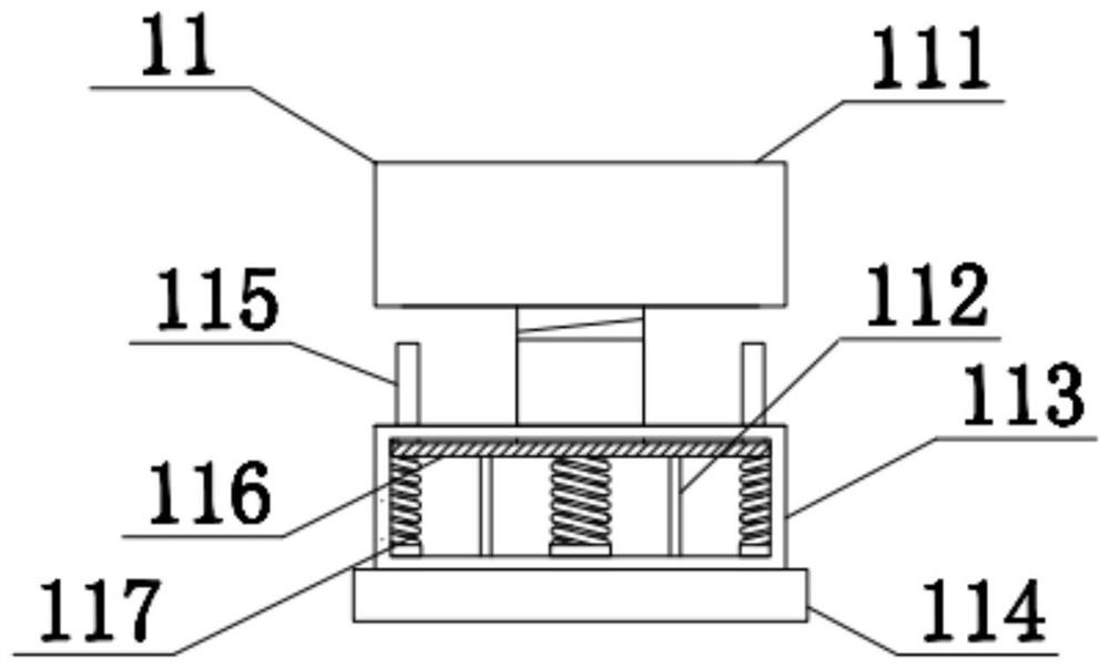
[0028] see Figure 1-5 , a substation automatic control lightning protection system, including a box body 1, the lower end of the box body 1 is fixedly connected with pillars 2 on the left and right sides, the lower end of the box body 1 is provided with a push-up mechanism 3, and the push-up mechanism 3 is arranged on the lower end of the box body 1. The lower end of the lifting mechanism 3 is provided with a shock absorbing mechanism 12, and the lower end of the shock absorbing mechanism 12 is fixedly connected with a casing 5, and the inside of the casing 5 is provided with a starting assembly 13, and the inside of the casing 5 is rotatably connected with a shaft rod 6 , the left and right ends of the shaft 6 are provided with shifting wheels 7, the inside of the box 1 is fixedly connected with a mounting plate 8, the upper end of the box 1 is provided with a lifting mechanism 9, and the inside of the lifting mechanism 9 A transmission mechanism 10 is provided, the upper en...


PUM


Abstract

The invention discloses a transformer substation automatic control lightning protection and lightning triggering system which comprises a box body, the left side and the right side of the lower end of the box body are fixedly connected with supporting columns, the lower end of the box body is provided with a pushing and lifting mechanism, the lower end of the pushing and lifting mechanism is provided with a damping mechanism, and the lower end of the damping mechanism is fixedly connected with a case. According to the scheme, an electric push rod is controlled through a controller, a connecting block is pushed by the electric push rod to move towards the ground, the connecting block drives a movable plate to get close to the ground at the same time, and a damping mechanism and a case are arranged at the lower end of the movable plate; As the two ends of the shaft rod on the case are connected with the moving wheels, when the moving wheels touch the ground, the supporting column ascends, the controller starts a second motor, so that a second angle gear on the second motor drives a first angle gear on a shaft rod to rotate, and then the shaft rod rotates to drive a moving wheel to roll, so that the moving range of the lightning triggering device is enlarged, and the lightning receiving range is wider.

Description

technical field [0001] The invention relates to the field of lightning protection equipment, in particular to an automatic control lightning protection and induction system for substations. Background technique [0002] Lightning rods, also known as lightning rods, lightning rods, lightning arresters, and lightning rods, are devices used to protect buildings, tall trees, etc. from lightning strikes. When a thundercloud discharge approaches the ground, it distorts the ground electric field. At the top of the lightning rod, a space where the local electric field is concentrated is formed to influence the development direction of the lightning pilot discharge, guide the lightning to discharge to the lightning rod, and then introduce the lightning current into the earth through the grounding down conductor and the grounding device, so that the protected object is not struck by lightning. . [0003] In the prior art, the lightning protection device is mostly fixed in a specific...

Claims


Application Information

Patent Timeline
IPC IPC(8): H02G13/00
CPCH02G13/00H02G13/40H02G13/80H02G13/60Y02E10/72
Inventor 杨坤漓王爽杨双义李素婷
Owner ZHENGZHOU UNIV OF IND TECH
Why Eureka
Eureka Blog
Learn More