
Liquid drop target release position calculation method

A technology that releases position and calculation methods, applied in design optimization/simulation, special data processing applications, geometric CAD, etc., can solve problems such as high initial condition requirements, poor robustness, and low calculation efficiency, and achieve simplified calculation process and judgment process, improving accuracy and reliability, improving the effect of non-physical results

Active Publication Date: 2021-10-08
LOW SPEED AERODYNAMIC INST OF CHINESE AERODYNAMIC RES & DEV CENT
View PDF7 Cites 4 Cited by
  • Summary
  • Abstract
  • Description
  • Claims
  • Application Information

AI Technical Summary

Problems solved by technology

[0008] 1. In the prior art, the calculation of the droplet collection rate using the Lagrangian method requires a large number of trajectory calculations to describe the droplet collection characteristics, and the rationality of the initial condition setting directly affects the accuracy of the calculation results, and the judgment process is complicated , the calculation process is complex, the calculation efficiency is low and the robustness is poor, and the requirements for the initial conditions are high;
[0009] 2. In the process of calculating the droplet collection rate by the Lagrangian method in the prior art, interpolation technology must be used to transfer the droplet collection rate of the impact point structure to the wall grid unit
However, in actual simulation, the distribution of droplet impact points is usually random and scattered and partly distributed on the wall, which results in uneven distribution or small number of sample points. If this is used as a calculation sample, it will greatly reduce the accuracy of the load interpolation results Accuracy, there is human intervention in the interpolation results, and it has great unreliability

Method used


Image

  • Liquid drop target release position calculation method
  • Liquid drop target release position calculation method
  • Liquid drop target release position calculation method

Examples


Embodiment Construction

[0037] The following description provides many different embodiments, or examples, for implementing various features of the invention. The elements and arrangements described in the following specific examples are only used to express the present invention in a concise manner, and are only used as examples rather than limiting the present invention.

[0038] In describing the present invention, it is to be understood that the terms "upper", "lower", "front", "rear", "left", "right", "vertical", "horizontal", "top", " The orientation or positional relationship indicated by "bottom", "inner", "outer", etc. is based on the orientation or positional relationship shown in the drawings, and is only for the convenience of describing the present invention and simplifying the description, rather than indicating or implying the referred device or Elements must have certain orientations, be constructed and operate in certain orientations, and therefore should not be construed as limitati...


PUM


Abstract

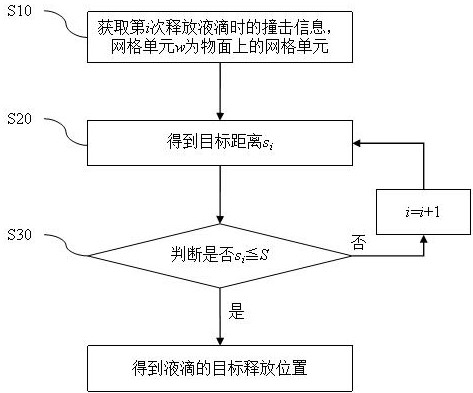
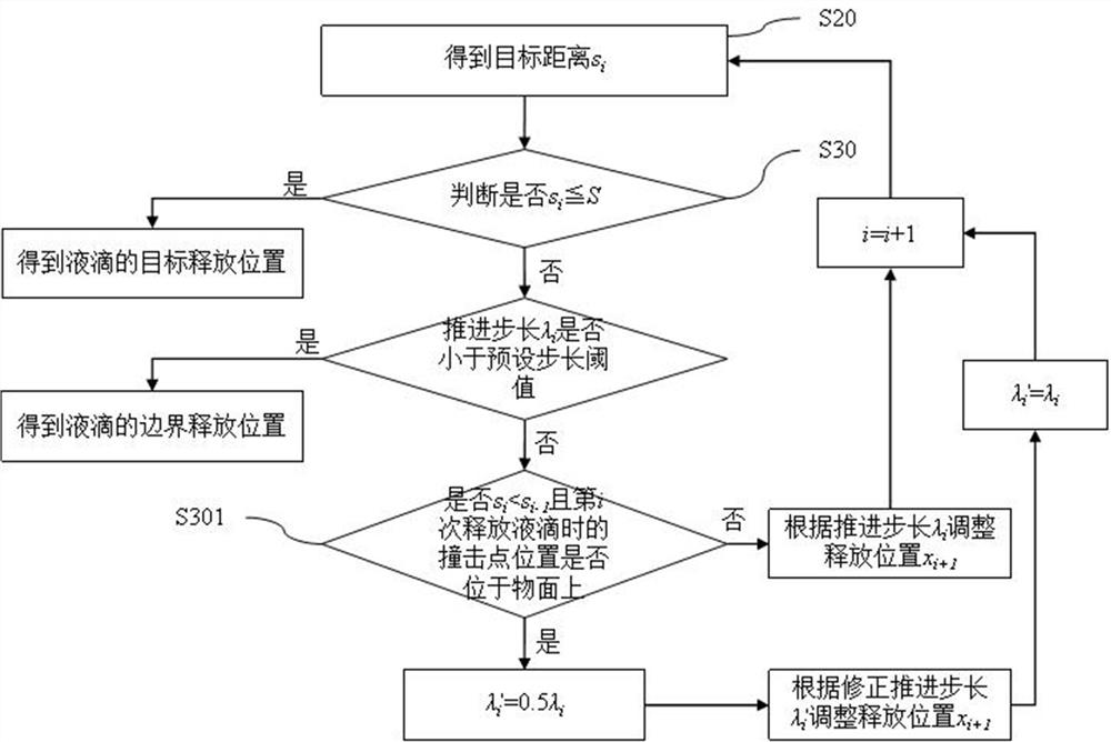
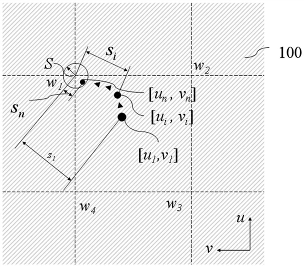
The invention is suitable for the technical field of liquid drop impact characteristic simulation, and provides a liquid drop target release position calculation method, which comprises the following steps: obtaining impact information when a liquid drop is released for the i time, the impact information comprising an impact point position when the liquid drop is released for the i time and a grid unit where the impact point position is located when the liquid drop is released for the i time, obtaining a release position xi when the liquid drop is released for the i time; obtaining a target distance si according to the distance between the impact point position and the target angular point when the liquid drop is released for the i time; until si<=S, determining that the release position xi is the target release position of the liquid drop. The liquid drop target release position calculation method has the advantages of being simple in calculation, efficient in calculation, good in robustness and high in calculation result precision.

Description

technical field [0001] The invention belongs to the technical field of droplet impact characteristic simulation, and in particular relates to a method for calculating a target release position of a droplet. Background technique [0002] Numerical simulation of icing in aircraft icing is an important means to study the characteristics of aircraft icing, which can meet the guidelines of a large number of operating conditions. In the calculation process of the aircraft icing value, the calculation of the droplet collection rate on the object surface is involved, and the calculation accuracy of the droplet collection rate will directly affect the accuracy of the ice shape prediction results. [0003] At present, the Lagrangian method is one of the commonly used methods for calculating droplet impact characteristics. The Lagrangian method has the advantages of high motion trajectory accuracy and strong dynamic performance tracking ability, and does not introduce numerical dissipa...

Claims


Application Information

Patent Timeline
Patent Type & Authority Applications(China)
IPC IPC(8): G06F30/15G06F30/23G06F111/10
CPCG06F30/15G06F30/23G06F2111/10
Inventor 任靖豪易贤王强李维浩刘宇
Owner LOW SPEED AERODYNAMIC INST OF CHINESE AERODYNAMIC RES & DEV CENT
Learn More