Ice shape measuring device and measuring method for icing wind tunnel test

A measuring device and a technology for wind tunnel testing, applied in the field of wind tunnel testing, can solve the problems of inability to accurately measure the ice shape position to be measured, waste of test materials, long preparation process for ice shape measurement, etc. Simple, reduce the effect of test consumables

Inactive Publication Date: 2021-10-08
LOW SPEED AERODYNAMIC INST OF CHINESE AERODYNAMIC RES & DEV CENT
View PDF10 Cites 2 Cited by
  • Summary
  • Abstract
  • Description
  • Claims
  • Application Information

AI Technical Summary

Problems solved by technology

[0005] 1. Since the position of the ice shape to be measured is different on the surface of the model, and the line type of the model surface is different, the support plate used to support the graph paper and the notch shape line at the front end of the graph paper in the test are also different, so In each test, it is necessary to prepare the support plate and graph paper in advance, so that the gaps of the support plate and the graph paper are consistent with the surface molding line of the model at the position to be tested; this leads to a long preparation process for ice shape measurement and a large amount of test materials. waste of
[0006] 2. If it is necessary to temporarily increase the position of the ice shape to be measured during the test, there is no way to accurately measure the temporarily increased position of the ice shape to be tested because there is no support plate and graph paper that are consistent with the model line on the surface of the model to be tested.

Method used


Image

  • Ice shape measuring device and measuring method for icing wind tunnel test
  • Ice shape measuring device and measuring method for icing wind tunnel test
  • Ice shape measuring device and measuring method for icing wind tunnel test

Examples


Embodiment 1

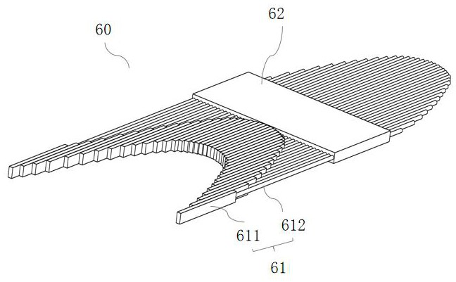
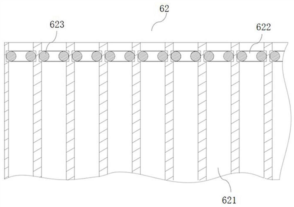
[0041] An icing wind tunnel test ice shape measurement device, such as figure 1 , figure 2 As shown, it includes an inserting board 62 and a plurality of pins 61; the inserting pins 61 include a square tube section 611 and a round tube section 612 fixedly connected to each other; a plurality of pin holes 621 are arranged side by side on the inserting plate 62, and the inserting pins 62 are arranged side by side. The round tube section 612 of the needle 61 passes through the pin hole 621 and can slide in the pin hole 621; the square tube section 611 of a plurality of the pins 61 is located on the same side of the insert plate 62; The upper plane of the square pipe section 611 is coplanar with the upper surface of the inserting plate 62 .

[0042] Thus, during the test, the graph paper is placed on the plane formed by the upper plane of the square pipe section 611 and the upper surface of the inserting plate 62 to prevent the graph paper from being wrinkled and affecting the a...

Embodiment 2

[0047]This embodiment relates to a method for measuring ice shape in an icing wind tunnel test. The ice shape measuring device for an icing wind tunnel test as described in Embodiment 1 is used. Include the following steps:

[0048] S10. cutting the ice shape to obtain the ice shape gap;

[0049] The method of cutting the ice shape is well known in the art, and will not be repeated here, and the ice shape cutting method in Embodiment 4 of the present invention can also be used.

[0050] S20. Adjusting a plurality of pins 61 so that the profiled lines surrounded by the tops of the multiple square pipe sections 611 are the same as the profiled lines of the ice shape acquisition position model to be measured;

[0051] At this time, since the position of the ice shape to be measured has been set in advance, the operator can obtain the profile curve data of the position of the ice shape to be measured according to the profile data of the model, and adjust the pin 61 according to t...

Embodiment 3

[0058] This embodiment relates to a method for measuring ice shape in an icing wind tunnel test, using an ice shape measuring device for an icing wind tunnel test as described in Embodiment 1. The difference from Embodiment 2 is that in this embodiment To measure the ice accretion and ice shape at the temporarily increased measurement position, or when the location of the ice shape to be measured is unknown in advance, the following steps are included:

[0059] S10. cutting the ice shape to obtain the ice shape gap;

[0060] S20. Adjusting a plurality of pins 61 so that the profiled lines surrounded by the tops of the multiple square pipe sections 611 are the same as the profiled lines of the ice shape acquisition position model to be measured;

[0061] At this time, because the profile line of the ice shape acquisition position model to be measured is not known in advance, during the test, the ice shape measuring device 60 is inserted into the cut ice shape gap, and the inser...


PUM


Abstract

The invention belongs to the technical field of wind tunnel tests, and provides an ice shape measuring device and measuring method for an icing wind tunnel test. The measuring device comprises an insertion plate and a plurality of insertion pins; each insertion pin comprises a square tube section and a round tube section which are fixedly connected with each other; a plurality of insertion pin holes are formed in the insertion plate side by side, and the circular tube sections of the insertion pins penetrate through the insertion pin holes and can slide in the insertion pin holes; the square tube sections of the plurality of insertion pins are positioned on the same side of the insertion plate; and the upper planes of the square tube sections are coplanar with the upper surface of the insertion plate. The ice shape measuring device for the icing wind tunnel test is composed of the insertion plate and the movable insertion pins; and when the ice shape measuring device is used, the positions of the movable insertion pins only need to be set according to the molded line of a to-be-measured ice shape obtaining position model; and therefore, the inconvenience that a supporting plate needs to be prepared again before each measurement in the prior art is avoided. The measuring device disclosed by the invention is simple to operate and can be repeatedly used, so that test time consumption and test consumables are greatly reduced.

Description

technical field [0001] The invention relates to the technical field of wind tunnel tests, in particular to an ice shape measurement device and a measurement method for icing wind tunnel tests. Background technique [0002] When the aircraft passes through the low-temperature cloud layer rich in supercooled liquid droplets at low speed, icing is prone to occur on the windward surface, which seriously threatens the flight safety of the aircraft. Carrying out aircraft model icing test in icing wind tunnel has become an important link in the design and verification of aircraft anti-icing system. [0003] In the aircraft model icing test, it is necessary to accurately obtain the 2-dimensional cross-sectional shape of the ice on the model surface (referred to as ice shape). The accuracy and speed of ice shape acquisition directly affect the quality and efficiency of the test. At present, the ice shape acquisition in the icing wind tunnel mainly adopts a hot knife cutting device. ...

Claims


Application Information

Patent Timeline
Patent Type & Authority Applications(China)
IPC IPC(8): G01M9/02G01M9/04G01M9/08
CPCG01M9/02G01M9/04G01M9/08
Inventor 张平涛郭龙王梓旭郭向东易贤赵照
Owner LOW SPEED AERODYNAMIC INST OF CHINESE AERODYNAMIC RES & DEV CENT
Why Eureka
Try Eureka