Solar collector with protection component

A technology for solar collectors and solar energy collection, applied in the directions of solar collectors, solar collector safety, solar collector shells, etc., can solve problems such as solar collector tube corrosion, safety hazards, shaking, etc., and achieve installation and fixation Good effect, easy to clean, and stable rotation

Inactive Publication Date: 2021-10-08
南通大鹏光电有限公司
View PDF4 Cites 0 Cited by
  • Summary
  • Abstract
  • Description
  • Claims
  • Application Information

AI Technical Summary

Problems solved by technology

[0003] When the solar collector is installed on the wall for use, because the position is low, people will accidentally touch it during normal use, causing the solar collector tube to break or shake, which has a great potential safety hazard. In bad weather, such as hail, it is necessary to suspend the use of solar collectors, and at the same time prevent hail from damaging the solar collector tubes. The common way is to use objects to block the solar collectors, but when the wind is too strong, the blocking effect will be greatly improved. Reduced, it is impossible to fully protect the solar collector pipes, and in normal use, dust particles and rainwater in the air will accumulate around the solar collector pipes due to no one cleaning them up. When dust and rainwater around the collector pipes When the accumulation time is long, the surface of the collection tube will be covered, which will affect the use of the solar collector. If it is not cleaned in time, the solar collector tube itself will be corroded. The common cleaning method is to clean it manually, and it cannot touch the place during cleaning. The dust cannot be cleaned, and there is still a large amount of residual dust sticking to the collection pipe, or deposited at the installation connection of the collection pipe, which will affect the use of the solar collection pipe

Method used


Image

  • Solar collector with protection component
  • Solar collector with protection component
  • Solar collector with protection component

Examples


Embodiment Construction

[0023] The following will clearly and completely describe the technical solutions in the embodiments of the present invention with reference to the accompanying drawings in the embodiments of the present invention. Obviously, the described embodiments are only some, not all, embodiments of the present invention.

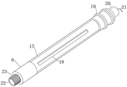
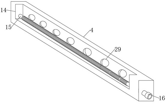
[0024] refer to Figure 1-5 , a solar collector with a protective assembly, comprising a mounting plate 1, a top plate 2 and a bottom plate 3 are respectively installed at the two ends of the mounting plate 1, a placement plate 9 is installed at one end of the top of the mounting plate 1, and the top of the mounting plate 1 is away from One end of the placement plate 9 is equipped with a fixed plate 4, the placement plate 9 is fixed on the side of the top plate 2, the fixed plate 4 is fixed on the side of the bottom plate 3, and one side of the fixed plate 4 is equidistantly provided with several installation holes 29, the fixed plate 4 There is a mounting groove 14 ...


PUM


Abstract

The invention relates to the field of solar collectors, and particularly discloses a solar collector with a protection component. The solar collector comprises a mounting plate, wherein a top plate and a bottom plate are respectively installed at two ends of the mounting plate; a placement plate is installed at one end of the top of the mounting plate; a fixing plate is installed at one end, far away from the placement plate, of the top of the mounting plate; the placement plate is fixed to the side face of the top plate; the fixing plate is fixed to the side face of the bottom plate; a plurality of mounting holes are formed in one side of the fixing plate at equal intervals; a mounting groove is formed in the other side of the fixing plate; a threaded rod is installed in the mounting groove; one end of the threaded rod is rotationally sleeved with the inner wall of the mounting groove; and the other end of the threaded rod penetrates through the fixing plate and is fixedly sleeved with an adjusting block. The solar collector can be protected to different extents through a protective net and a protective sleeve in severe weather and normal use, the solar collector is protected to a great extent, and meanwhile, dust and rainwater are convenient to clean.

Description

technical field [0001] The invention relates to the technical field of solar collectors, in particular to a solar collector with a protective component. Background technique [0002] The solar collector is composed of a glass box bonded by glass plates with an adhesive and a dark heat-absorbing material inside the box. There are water inlet and outlet pipes on the glass box to facilitate water inlet and outlet. It is similar to a huge thermometer. It consists of two glass tubes, one inside the other, which can collect the heat from the sun and transmit it to the liquid circulating through the tubes. Installed on the wall is a solar energy collection device that shines on the outside of the wall. This causes the air in the middle of the device to be heated. The heated air moves upwards and is sent to the room by the exhaust fan to complete the whole heat preservation process. The heat dissipated from the building surface is brought back to the interior of the building thro...

Claims


Application Information

Patent Timeline
Patent Type & Authority Applications(China)
IPC IPC(8): F24S10/70F24S40/10F24S80/30F24S80/40
CPCF24S10/742F24S80/40F24S80/30F24S40/10Y02E10/44Y02B10/20
Inventor 蔡宇
Owner 南通大鹏光电有限公司
Why Eureka
Try Eureka