A flow limiting valve for industrial water room with self-cleaning function

A technology of flow limitation and function, which is applied in the field of flow limitation valves used in industrial water houses, can solve the problems of not being able to close quickly, reduce the sealing effect, and wear of the gate plate, so as to improve the safety of use, improve the sealing effect, and improve the sealing accuracy. Effect

Active Publication Date: 2021-11-26
法图尔智能装备江苏有限公司
View PDF1 Cites 0 Cited by
  • Summary
  • Abstract
  • Description
  • Claims
  • Application Information

AI Technical Summary

Problems solved by technology

[0005] In order to solve the above-mentioned technical problems, the present invention provides a flow limiting valve for industrial water room with self-cleaning function to solve the problem that the water flow is cut off by the gate plate when it is closed, and the gate plate wears seriously when it is used for a long time. The sealing effect is reduced, it is not easy to use, and because of the high pressure of the water flow in the industrial water room, when the pipe or faucet is suddenly damaged, it will take a certain time for the staff to close it, and it cannot be closed quickly. The residue and rust in the water cannot be cleaned during use, which affects the water quality.

Method used


Image

  • A flow limiting valve for industrial water room with self-cleaning function
  • A flow limiting valve for industrial water room with self-cleaning function
  • A flow limiting valve for industrial water room with self-cleaning function

Examples


Embodiment

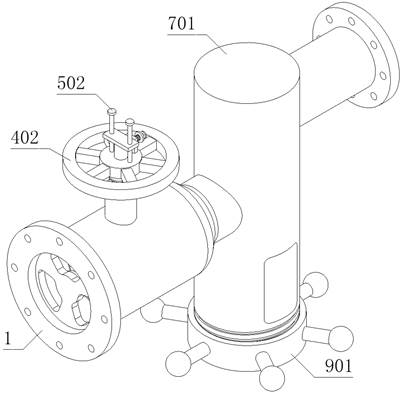
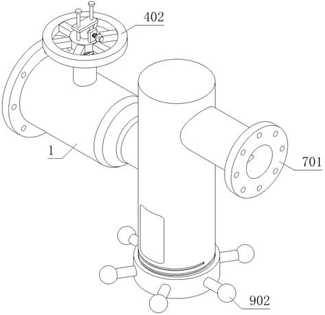
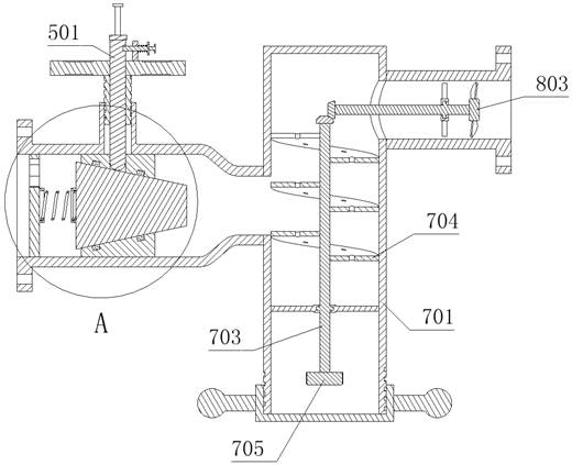
[0070] as attached figure 1 to attach Figure 13 Shown:

[0071] The present invention provides a flow limiting valve for an industrial water room with self-cleaning function, which includes a valve body 1; side; the top of the valve body 1 is equipped with an adjustment device 4, and the inside of the adjustment device 4 is equipped with a pusher 5, and the top of the adjustment device 4 is installed with a limit portion 6; a cleaning device 7, and the cleaning device 7 is installed on the valve body 1 On the right side, and the bottom of the cleaning device 7 is equipped with a collecting device 9 , and the inside of the cleaning device 7 is equipped with a drive mechanism 8 .

[0072] Such as Figure 5 As shown, the sealing device 2 includes: a sealing block 201, which is fixedly connected with the valve body 1;

[0073] There are two sealing rings 202, and there are two sealing rings 202, and the two sealing rings 202 are fixedly installed inside the sealing block 201,...


PUM


Abstract

The invention provides a flow limiting valve for an industrial water room with self-cleaning function, which includes a valve body; a sealing device and a flow limiting mechanism are installed inside the valve body, and the flow limiting mechanism is located on the left side of the sealing device; An adjustment device is installed on the top of the valve body, and a pushing part is installed inside the adjustment device, and a limit part is installed on the top of the adjustment device; the cleaning device is installed on the right side of the valve body, and a collection device is installed at the bottom of the cleaning device , and the inside of the cleaning device is equipped with a driving mechanism. In the present invention, the sealing block is fixedly connected with the valve body, and two sealing rings are fixedly installed inside the sealing block, thereby improving the sealing effect between the sealing block and the moving block. Because a spring is fixedly installed between the limit plate and the moving block, the moving block moves to the right under the action of the spring when the present invention is closed, and the cross section of the moving block is a trapezoidal structure, which is then sealed under the action of the spring and water flow pressure. Tight fit between blocks and moving blocks.

Description

technical field [0001] The invention belongs to the technical field of valves, and more specifically relates to a flow limiting valve for an industrial water room with its own cleaning function. Background technique [0002] Valves are the control components in the fluid conveying system, with the functions of cut-off, adjustment, diversion, prevention of reverse flow, pressure stabilization, diversion or overflow pressure relief; valves can be used to control air, water, steam, various corrosive media, mud , oil, liquid metal and radioactive media and other types of fluid flow. [0003] For example, in the patent with application number CN201210199191.X, a flow limiting shut-off valve is disclosed, including a flow shut-off valve and a shut-off valve; the flow shut-off valve includes a valve body, a piston and a biasing component; There is a through cavity, and the water outlet of the through cavity is provided with a sealing seat; the piston can be axially reciprocated an...

Claims


Application Information

Patent Timeline
Patent Type & Authority Patents(China)
IPC IPC(8): F16K1/38F16K1/32F16K27/02F16K31/60
CPCF16K1/38F16K1/32F16K27/0254F16K31/60
Inventor 王佳伟
Owner 法图尔智能装备江苏有限公司
Why Eureka
Try Eureka