Color cathode ray tube
A cathode ray tube, color technology, applied in the direction of cathode ray tube/electron beam tube, screen tube, discharge tube, etc., can solve the problems of difficult curved surface maintaining intensity, interval change, and deterioration of phosphor screen quality.
- Summary
- Abstract
- Description
- Claims
- Application Information
AI Technical Summary
Problems solved by technology
Method used
Image
Examples
Embodiment 1
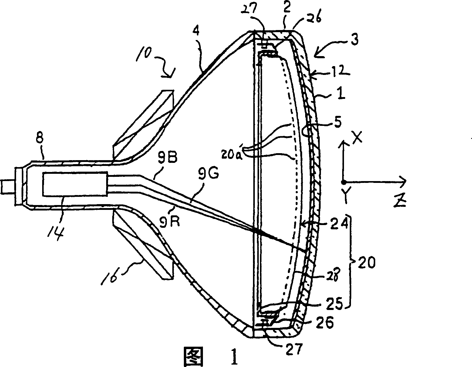
[0032] As shown in FIG. 1, a color cathode ray tube has a casing 10 made of glass, which includes a panel 1 having a nearly rectangular shape and a glass screen 3 with a skirt portion 2 arranged vertically at an edge portion of the panel, and The funnel 4 to which the skirt part 2 is connected. The panel 1 has an effective portion 12 of approximately short shape formed by a curved surface, the effective portion has a horizontal axis X and a vertical axis Y passing through the tube axis Z and perpendicular to each other.
[0033] On the inner surface of the effective portion 12 is formed a fluorescent screen 5 composed of, for example, a large number of stripe-shaped three-color fluorescent screens extending parallel to the vertical axis and emitting blue, green, and red light. A shadow mask 20 having a nearly rectangular shape is provided inside the envelope 10 to face the phosphor screen 5 . Inside the neck 8 of the funnel 4 is provided an inline electron gun 14 emitting thr...
Embodiment 2
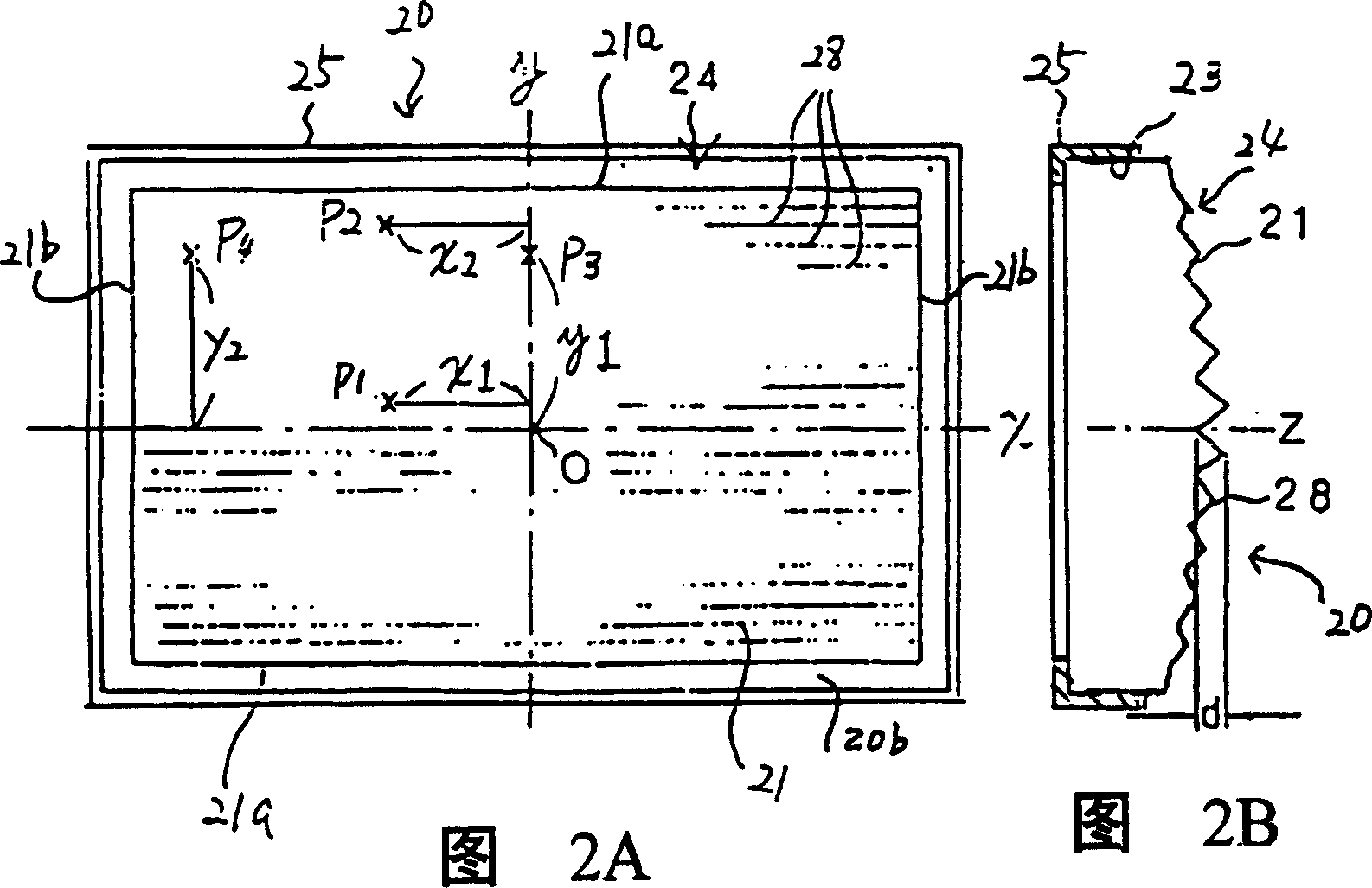
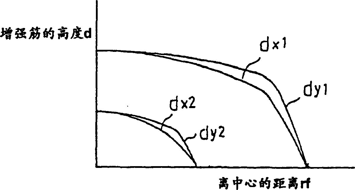
[0056] In other embodiments of the present invention as shown in FIG. 8, the shadow mask body 24 of the shadow mask 20, when the width between the long sides 21a of the effective surface 21 is ds, is centered on the long axis X and has ds / 3 In the wide area, there are several belt-shaped reinforcing ribs 28 extending parallel to the long axis X. The protruding heights of these reinforcing ribs 28 are set so as to satisfy the aforementioned conditions (1) and (2). In addition, other structures are the same as those of the foregoing embodiments, and their descriptions are omitted here.
[0057] In the case of a shadow mask with such a structure, the reinforcing ribs 28 do not affect the formation of the fluorescent screen, and the curved surface holding strength of the effective surface 21 can be improved, and the deformation of the shadow mask in the manufacturing process can be reduced and the shadow mask can be reduced during the operation of the color cathode ray tube. Bump...
Embodiment 3
[0059] Additionally, if Figure 9 In the illustrated embodiment, when the effective surface 21 of the shadow mask 20 is set to have a width dL between the short sides 21b of the effective surface 21, in a region centered on the short axis Y and having a width of dL / 3, there are Several belt-shaped reinforcing ribs 28 extending parallel to the axis y. The protruding heights of these reinforcing ribs 28 are set so as to satisfy the aforementioned conditions (1) and (2). In addition, other structures are the same as those of the foregoing embodiments, and their descriptions are omitted here.
[0060] In the case of a shadow mask with such a structure, the reinforcing ribs 28 do not affect the formation of the fluorescent screen, and the curved surface holding strength of the effective surface 21 can be improved, and the deformation of the shadow mask in the manufacturing process can be reduced and the shadow mask can be reduced during the operation of the color cathode ray tube....
PUM
 Abstract
Description
Claims
Application Information
 - Generate Ideas
- Intellectual Property
- Life Sciences
- Materials
- Tech Scout
- Unparalleled Data Quality
- Higher Quality Content
- 60% Fewer Hallucinations
Browse by: Latest US Patents, China's latest patents, Technical Efficacy Thesaurus, Application Domain, Technology Topic, Popular Technical Reports.
© 2025 PatSnap. All rights reserved.Legal|Privacy policy|Modern Slavery Act Transparency Statement|Sitemap|About US| Contact US: help@patsnap.com


