
Construction waste treatment equipment

A technology for processing equipment and construction waste, applied in construction waste recycling, supply device, recycling technology and other directions, can solve the problems of low molding efficiency, inconvenient slurry transfer, inconvenient product transportation, etc., to strengthen structural strength, simple and efficient equipment , The effect of saving the transfer process

Active Publication Date: 2021-10-08
CHINA CONSTR FIRST BUILDING GRP CORP LTD
View PDF17 Cites 3 Cited by
  • Summary
  • Abstract
  • Description
  • Claims
  • Application Information

AI Technical Summary

Problems solved by technology

The existing construction waste treatment process generally includes construction waste recycling, construction waste crushing and construction waste classification, and the reuse of classified waste. Using construction waste to produce unburned bricks is an excellent solution for construction waste treatment and reuse. The conventional process Including crushing, screening, stirring and mixing, pouring molding, natural curing, etc. However, the mixing and molding process is generally located in two places, and the transfer of the slurry after stirring is inconvenient, and for the molding stage, semi-automatic molding machines or full-automatic molding are mostly used machine for forming, and then transported to other places for natural maintenance, there are defects of low forming efficiency and inconvenient transportation of formed products, although a construction waste treatment system is disclosed in the invention patent with application number 201910729719.1, which can combine forming with The comprehensive maintenance is completed on one piece of equipment, but the system lacks the compaction process for unburned bricks, and the strength of the unburned bricks produced is difficult to meet the requirements. Transferring out is time-consuming and labor-intensive

Method used


Image

  • Construction waste treatment equipment
  • Construction waste treatment equipment
  • Construction waste treatment equipment

Examples


Embodiment Construction

[0025] The present invention will be further described in detail below in conjunction with the accompanying drawings, so that those skilled in the art can implement it with reference to the description.

[0026] It should be noted that, in the description of the present invention, the terms "horizontal", "vertical", "upper", "lower", "front", "rear", "left", "right", "vertical", The orientation or positional relationship indicated by "horizontal", "top", "bottom", "inner", "outer", etc. is based on the orientation or positional relationship shown in the drawings, and is only for the convenience of describing the present invention and simplifying the description, and It is not to indicate or imply that the device or element referred to must have a particular orientation, be constructed in a particular orientation, or operate in a particular orientation, and thus should not be construed as limiting the invention.

[0027] Such as Figure 1~4 As shown, the present invention prov...


PUM


Abstract

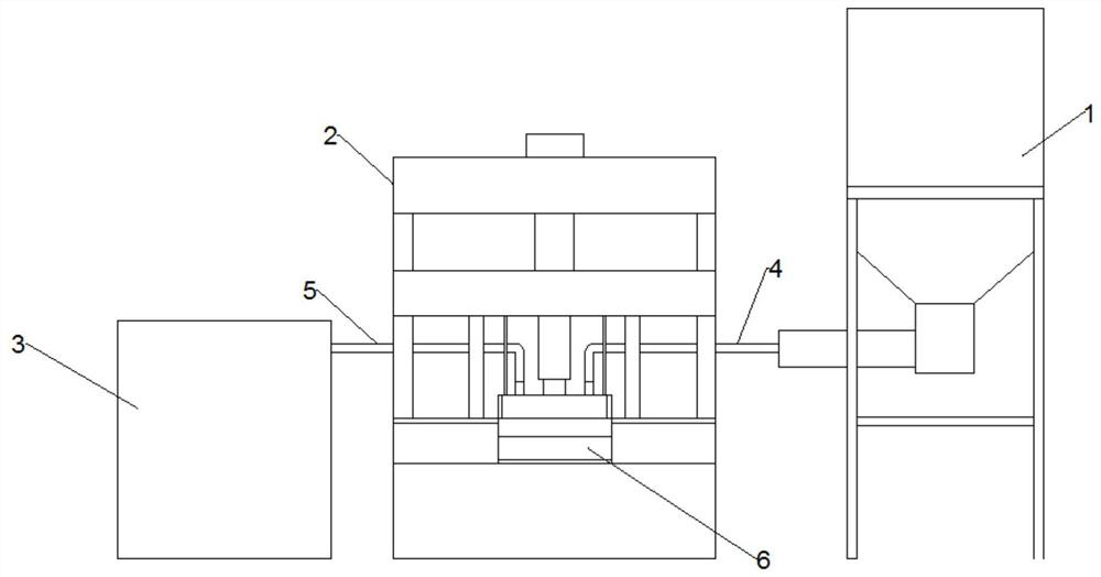
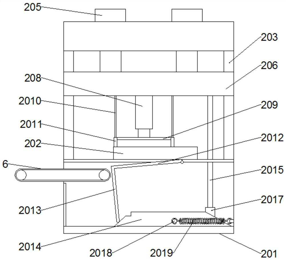
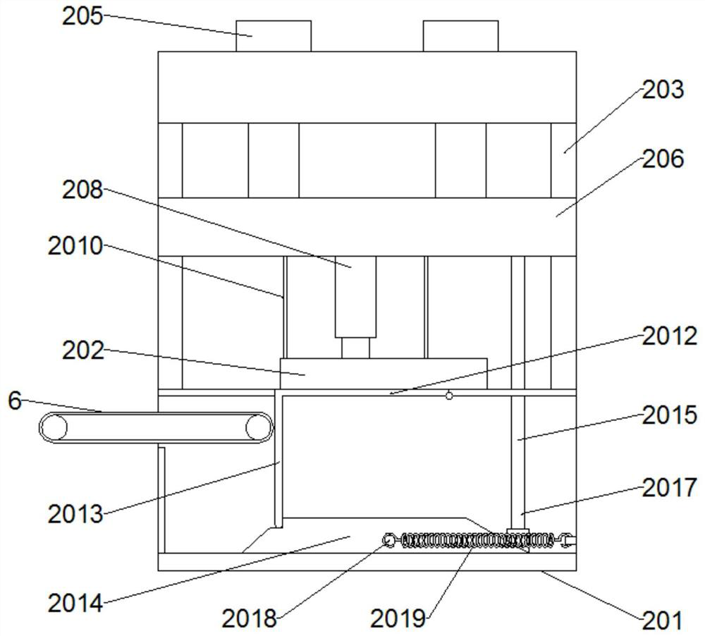
The invention discloses construction waste treatment equipment which comprises a stirring assembly and a forming assembly. The forming assembly comprises a machine station, and a pair of parallel and opposite first side templates are arranged on the top face of the machine station; the four corners of the top face of the machine station are each provided with a vertical guide column, and the top ends of the four guide columns are jointly connected with a top plate right facing the top face of the machine station; a first hydraulic machine is arranged on the top plate, and a piston rod of the first hydraulic machine stretches downwards; the lower end of the piston rod of the first hydraulic machine is connected with a movable plate; a second hydraulic machine is arranged on the movable plate, a piston rod of the second hydraulic machine stretches downwards, and the lower end of the piston rod of the second hydraulic machine is connected with a pressing plate; the movable plate is connected with a pair of parallel and opposite second side templates through first connecting rods; and when the piston rod of the first hydraulic machine is in the maximum stroke, the second side templates are inserted between the first side templates to form a surrounding cavity. According to the construction waste treatment equipment, a plurality of manufacturing procedures for baking-free bricks are integrated and completed through the equipment, and the transferring procedure is omitted.

Description

technical field [0001] The invention relates to the field of garbage disposal equipment. More specifically, the present invention relates to a construction waste treatment device. Background technique [0002] Construction waste refers to the dregs, spoils, waste materials, silt and other wastes generated during the construction, laying or demolition, and repair of various buildings, structures, and pipe networks by buildings, construction units, or individuals. The existing construction waste treatment process generally includes construction waste recycling, construction waste crushing and construction waste classification, and the reuse of classified waste. Using construction waste to produce unburned bricks is an excellent solution for construction waste treatment and reuse. The conventional process Including crushing, screening, stirring and mixing, pouring molding, natural curing, etc. However, the mixing and molding process is generally located in two places, and the ...

Claims


Application Information

Patent Timeline
Patent Type & Authority Applications(China)
IPC IPC(8): B28B3/02B28B13/02
CPCB28B3/02B28B13/02Y02W30/58
Inventor 周冀伟孔巍史红玉马琦越胡先训
Owner CHINA CONSTR FIRST BUILDING GRP CORP LTD
Learn More