An automatic lamination device for transformer iron core

A technology of transformer iron core and lamination device, which is applied in the direction of transformer/inductor core, inductance/transformer/magnet manufacturing, transformer/inductance parts, etc., which can solve the horizontal deviation of silicon steel sheet and damage of silicon steel sheet, etc. problem, to achieve the effect of avoiding friction, avoiding extrusion force and friction force

Active Publication Date: 2021-11-16
昌航电气有限公司
View PDF7 Cites 0 Cited by
  • Summary
  • Abstract
  • Description
  • Claims
  • Application Information

AI Technical Summary

Problems solved by technology

[0003] At present, the following problems exist in the manufacturing process of transformer core laminations: (1) In order to ensure the alignment of each layer of silicon steel sheets, it is necessary to use a limit rod to limit the silicon steel sheets. When the upper layer of silicon steel sheets is stacked on the lower layer of silicon steel sheets, the silicon steel sheets The edge is prone to friction with the limit rod, causing damage to the silicon steel sheets; (2) After the silicon steel sheets are stacked, the stacked silicon steel sheets need to be lifted up for a certain distance to install the splint. During this process, the silicon steel sheets are easy to There will be a horizontal offset, resulting in extrusion and friction with the limit rod, which will also cause damage to the silicon steel sheet

Method used


Image

  • An automatic lamination device for transformer iron core
  • An automatic lamination device for transformer iron core
  • An automatic lamination device for transformer iron core

Examples


Embodiment Construction

[0031] The embodiments of the present invention will be described in detail below with reference to the accompanying drawings, but the present invention can be implemented in many different ways defined and covered by the claims.

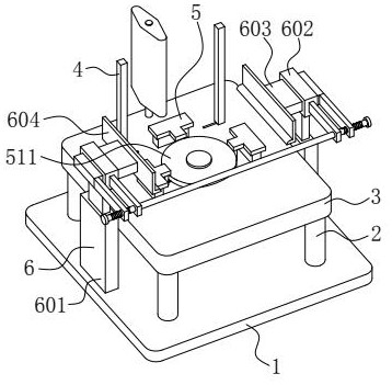
[0032] Such as figure 1As shown, this embodiment provides an automatic lamination device for transformer cores, for such as Figure 8 The silicon steel sheets shown are stacked, including a horizontal base plate 1 , a platform 3 is fixedly installed above the base plate 1 through a support column 2 , and a positioning mechanism 4 and a supporting mechanism 5 are installed above the base plate 1 .

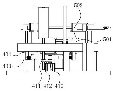
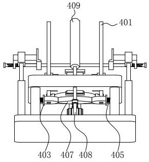
[0033] Such as figure 2 , image 3 and Figure 5 As shown, the positioning mechanism 4 includes two vertical rods 401 that are horizontally slidably installed on the platform 3 along the same straight line. A mobile plate 403 is fixed vertically on the top, and a fixed plate 404 parallel to the mobile plate 403 is fixedly installed on the bottom surf...


PUM


Abstract

The invention belongs to the technical field of transformer accessories manufacturing, and in particular relates to an automatic lamination device for transformer iron cores, comprising a horizontal base plate, a platform is fixedly installed above the base plate through a support column, a positioning mechanism and a supporting mechanism are installed above the base plate, and a base plate is installed on the base plate. There is a stacking mechanism; in the process of stacking the upper layer silicon steel sheet on the lower layer silicon steel sheet, the silicon steel sheet does not contact the vertical rod, so as to avoid the situation of friction between the edge of the silicon steel sheet and the vertical rod; In the process of installing the splint after the sheets are stacked into an iron core, the limiting effect on a single wedge block is released in turn, so that the lifting block and the supporting plate move downward under the action of their own gravity, and the supporting plate and the bottom surface of the bottom silicon steel sheet separation, so as to achieve the effect that the splint can be installed without lifting the silicon steel sheet, and avoid the situation of squeezing force and friction between the silicon steel sheet and the vertical rod.

Description

technical field [0001] The invention belongs to the technical field of transformer accessories production, and in particular relates to an automatic lamination device for transformer iron cores. Background technique [0002] The iron core is the main magnetic circuit part of the transformer. It is usually stacked by hot-rolled or cold-rolled silicon steel sheets with high silicon content and coated with insulating paint on the surface. The iron core and the coil wound on it form a complete electromagnetic induction system. During the production process of the transformer iron core, the silicon steel sheets should be stacked together first, and then the two sides of the iron core should be clamped with splints. [0003] At present, the following problems exist in the manufacturing process of transformer core laminations: (1) In order to ensure the alignment of each layer of silicon steel sheets, it is necessary to use a limit rod to limit the silicon steel sheets. When the u...

Claims


Application Information

Patent Timeline
Patent Type & Authority Patents(China)
IPC IPC(8): H01F41/02H01F27/26
CPCH01F41/0233H01F27/263
Inventor 李国粮陈怡凡
Owner 昌航电气有限公司
Why Eureka
Try Eureka